Intra-operative use of fluorescence spectroscopy and applications of same

a fluorescence spectroscopy and intraoperative technology, applied in the field of near-infrared optical detection, can solve the problems of subjective and often inconclusive, difficult visual distinction of structures, and further complicated situations, and achieve the effect of higher levels of auto-fluorescen

Active Publication Date: 2012-01-12
VANDERBILT UNIV
View PDF2 Cites 24 Cited by
  • Summary
  • Abstract
  • Description
  • Claims
  • Application Information

AI Technical Summary

Benefits of technology

[0029]In yet a further aspect, the present invention relates to a system for intraoperatively detecting the presence of infiltrating cells in the lymph nodes and surrounding tissues. In one embodiment, the process includes the steps of illuminating

Problems solved by technology

Due to their close proximity and tendency to blend into each other, many of these structures, specifically the parathyroid glands, are difficult to distinguish visually during endocrine surgery.
The situation is further complicated by its small size and variability in positi

Method used


Image

  • Intra-operative use of fluorescence spectroscopy and applications of same
  • Intra-operative use of fluorescence spectroscopy and applications of same
  • Intra-operative use of fluorescence spectroscopy and applications of same

Examples


example 1

[0074]This example in part illustrates a method or process, with corresponding apparatus or system, according to one embodiment of the present invention.

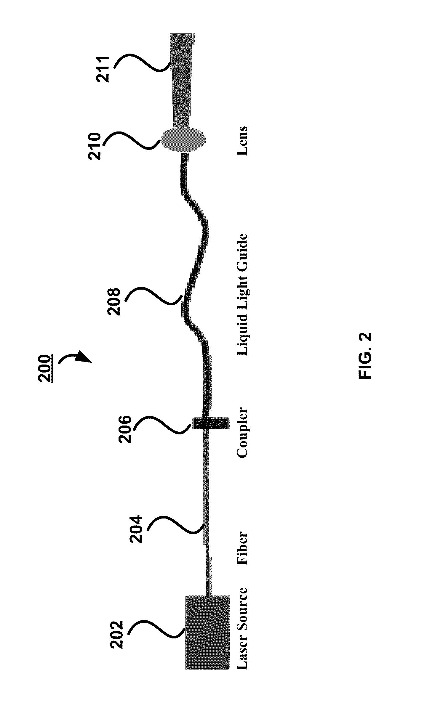
[0075]Referring now to FIG. 3E, a system 300E is schematically shown in a block diagram. The system 300E has a light source 302, which is designed to provide a beam of light with appropriate excitation wavelengths and energy so as to excite certain molecules of sample tissue 307, when receiving the beam of light, to generate auto-fluorescence emission. The system 300E also has a light delivery device 326, which is optically coupled with the light source 302 and delivers the beam of light from the light source 302 to the tissue 307. An optional filter 330 can be strategically positioned in an optical path 328 along which optical signals emitted from the tissue 307 responsive to the incident beam of light travel and utilized to reduce excess wavelengths and / or ambient light to ensure desirable optical signals to be detected. The syste...

example 2

[0089]This example in part illustrates a method or process, with corresponding apparatus or system, according to another embodiment of the present invention.

[0090]Referring now to FIG. 3C, a system 300C is schematically shown in a block diagram. The system 300C has a light source 302, which is designed to provide a beam of light with appropriate excitation wavelengths and energy so as to excite certain molecules of sample tissue 307, when receiving the beam of light, to generate auto-fluorescence emission. The system 300C also has a light delivery device 326, which is optically coupled with the light source 302 and delivers the beam of light from the light source 302 to the tissue 307. An optional filter 330 can be strategically positioned in an optical path 328 along which optical signals emitted from the tissue 307 responsive to the incident beam of light travel and utilized to reduce excess wavelengths and / or ambient light to ensure desirable optical signals to be detected. The s...

example 3

[0095]This example in part illustrates an apparatus or system, which can be utilized to practice a method or process according to one embodiment of the present invention.

[0096]Referring now to FIG. 3A, a system 300A is schematically shown in block diagram. The system 300A has a light source 302, which is designed to provide a beam of light with appropriate excitation wavelengths and energy so as to excite certain molecules of sample tissue 307, when receiving the beam of light, to generate fluorescence emission. The system 300A also has a light delivery and collection device 306, which is optically coupled with the light source 302 and delivers the beam of light from the light source 302 to the tissue 307 and collects optical signals emitted from the tissue 307 responsive to the incident beam of light. An optional filter 310 can be utilized to reduce excess wavelengths and / or ambient light to ensure desirable optical signals to be detected. The system 300A further has a detector 314...


PUM


Abstract

In one aspect, the present invention relates to a process for intra-operatively providing anatomical guidance in endocrine surgery. In one embodiment, the process includes the steps of illuminating tissues in the neck area of a living subject with a beam of light having a predetermined wavelength, obtaining Raman data from light scattered from the illuminated tissues, finding Raman signatures corresponding to thyroid or parathyroid tissues from the obtained Raman data, and identifying the thyroid or parathyroid tissues from the corresponding Raman signatures.

Description

[0001]This application is being filed as PCT International Patent application in the name of Vanderbilt University, a U.S. national corporation, Applicant for all countries except the U.S., and Anita Mahadevan-Jansen, Lisa White, John Phay, Constantine Paras, Elizabeth Kanter, Matt Keller, Nicole Gasparino, and Jennifer Whisenant, all U.S. residents, Applicants for the designation of the U.S. only, on 30 Jul. 2009.CROSS-REFERENCE TO RELATED PATENT APPLICATION[0002]This application claims priority to and the benefit of, pursuant to 35 U.S.C. §119(e), U.S. provisional patent application Ser. No. 61 / 137,520, filed Jul. 30, 2008, entitled “Intraoperative Use of Fluorescence Spectroscopy,” by Constantine Paras, Anita Mahadevan-Jansen, Matt Keller, John Phay and Lisa White, the contents of which is incorporated herein in its entirety by reference.[0003]This application also claims priority to and the benefit of, pursuant to 35 U.S.C. §119(e), U.S. provisional patent application Ser. No. 6...

Claims


Application Information

Patent Timeline
IPC IPC(8): A61B5/1455
CPCA61B5/0071A61B5/0075A61B5/0086A61B5/415G01N2201/0221A61B5/4227G01N21/6456G01N21/65G01N2021/6439A61B5/418A61B2505/05A61B34/20A61B2034/2055A61B5/742
Inventor MAHADEVAN-JANSEN, ANITAWHITE, LISAPHAY, JOHNPARAS, CONSTANTINE A.KANTER BARTZ, ELIZABETHKELLER, MATTHEW D.GASPARINO, NICOLEWHISENANT, JENNIFER GRAY
Owner VANDERBILT UNIV
Why Eureka
Try Eureka