Apparatus for osmotic power generation and desalination using salinity difference

a technology of osmotic power generation and desalination, applied in the direction of energy-based wastewater treatment, machines/engines, rotary clutches, etc., can solve the problems of insufficient water people may reliably have, large quantity of water on earth, and inability to continue the process of generating electricity, etc., to achieve the effect of reducing the pressure of salt water

Inactive Publication Date: 2012-01-19
KOREA INST OF MACHINERY & MATERIALS
View PDF2 Cites 55 Cited by
  • Summary
  • Abstract
  • Description
  • Claims
  • Application Information

AI Technical Summary

Benefits of technology

[0033]Another embodiment of the present invention provides an apparatus for osmotic power generation and desalination using a salinity difference, including: a forward osmotic membrane reactor including a first salt water position space through which supplied salt water passes, and a third salt water position space through which salt water having a salt concentration higher than that of salt water positioned in the first salt water position space passes, the first and third salt water position spaces being separated by a forward osmotic membrane; a reverse osmotic membrane reactor including a second salt water position space through which supplied salt water passes, and a fresh water position space in which fresh water is positioned, the second salt water position space and the fresh water position space being separated by reverse osmotic membrane; a high pressure pump connected at an upstream side of the reverse osmotic membrane reactor and pressurizing salt water supplied to the second salt water position space; a pressure reduction valve connected between the second salt water position space and the third salt water position space and reducing pressure of salt water supplied from the second salt water position space to the third salt water position space; and a turbine connected to a downstream side of the third salt water position space and driven by flow force of salt water discharged from the third salt water position space to produce electric energy.

Problems solved by technology

Waterpower generation using a dam, however, is disadvantageous in that generation cannot be continued when precipitation is small.
However, this scheme is disadvantageous in that it is available only in an area where seawater (the sea) and fresh water (river) meet.
Meanwhile, a great quantity of water exists on earth, but water people may reliably have is insufficient.
However, the scheme using a windmill is disadvantageous in that it can be driven only under a condition in which sufficient energy can be obtained through wind velocity.
However, in the forward osmosis process, a draw solution including a high concentration draw solute compared with seawater is used, it is difficult to separate the draw solute from the draw solution diluted by water moved through a forward osmotic membrane.
Meanwhile, the related art forward osmosis process also has a problem in which a considerably long period of time is required to desalinate seawater.

Method used


Image

  • Apparatus for osmotic power generation and desalination using salinity difference
  • Apparatus for osmotic power generation and desalination using salinity difference
  • Apparatus for osmotic power generation and desalination using salinity difference

Examples


first embodiment

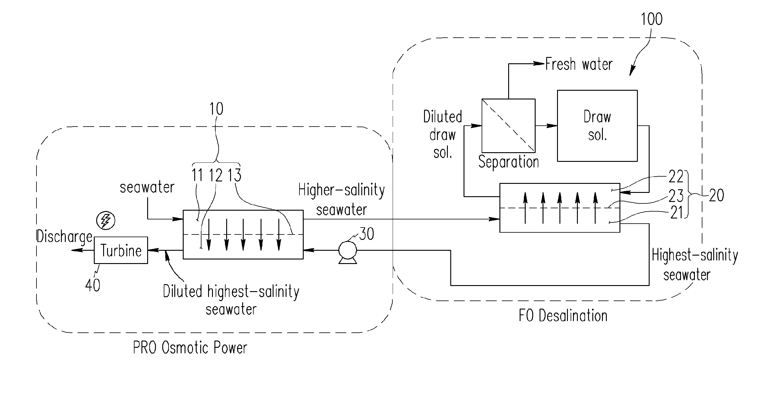
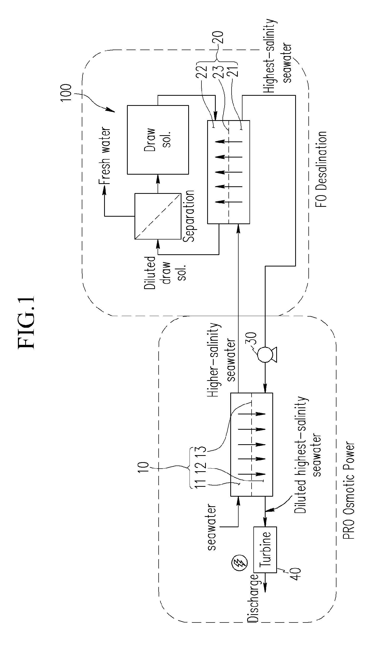
[0075]The apparatus for osmotic power generation and desalination according to the present invention illustrated in FIG. 1 is configured such that seawater goes through the first salt water position space 11 of the first osmotic membrane reactor 10, flows into the second salt water position space 21 of the second osmotic membrane reactor 20, and then passes through the third salt water position space 12 of the first osmotic membrane reactor 10.

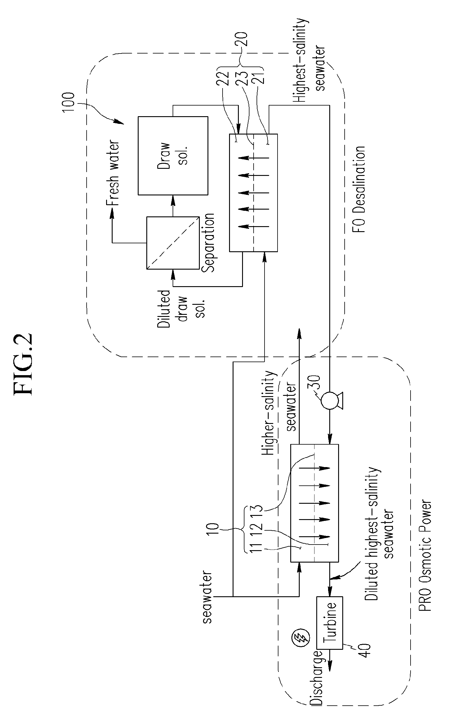
[0076]Meanwhile, in an apparatus for osmotic power generation and desalination according to a modification of the first embodiment of the present invention illustrated in FIG. 2 is configured such that seawater passing through the first salt water position space 11 of the first osmotic membrane reactor 10 and seawater passing through the second salt water position space 21 of the second osmotic membrane reactor 20 exist separately, and after seawater passes through the second salt water position space 21 of the second osmotic membrane reactor ...

second embodiment

[0126]FIG. 9 is a schematic view of an apparatus for osmotic power generation and desalination according to the present invention.

[0127]The apparatus for osmotic power generation and desalination according to the second embodiment of the present invention includes all the components of the apparatus according to the first embodiment of the present invention illustrated in FIG. 1, and further includes an energy recovery device (ERD) 51.

[0128]The energy recovery device (ERD) 51 is connected between the second salt water position space 21 of the second osmotic membrane reactor 20 and the high pressure pump 30 to allow seawater discharged from the second salt water position space 21 to pass therethrough. Also, seawater discharged from the third salt water position space 12 passes through the ERD 51.

[0129]The high pressure diluted high salinity seawater (or diluted highest salinity seawater) discharged from the third salt water position space 12 flows to be introduced into the ERD 51, is...

third embodiment

[0135]FIG. 11 is a schematic view of an apparatus for osmotic power generation and desalination according to the present invention.

[0136]The apparatus for osmotic power generation and desalination according to the third embodiment of the present invention includes a forward osmotic membrane reactor 10 and a reverse osmotic membrane reactor 60, and is driven by supplying brackish water to the forward osmotic membrane reactor 10 and the reverse osmotic membrane reactor 60.

[0137]The forward osmotic membrane reactor 10 includes the first salt water position space 11 through which supplied brackish water passes and the third salt water position space 12 through which brackish water having a higher concentration of salt than that of brackish positioned in the first salt water position space 11. The first salt water position space and the third salt water position space 12 are separated by a forward osmotic membrane 13.

[0138]The reverse osmotic membrane reactor 60 includes a second salt wa...


PUM

PropertyMeasurementUnit
pressureaaaaaaaaaa
salinityaaaaaaaaaa
concentrationaaaaaaaaaa

Abstract

An apparatus for osmotic power generation and desalination of seawater using a salinity difference is provided.
The apparatus for osmotic power generation and desalination using a salinity difference includes: a first osmotic membrane reactor having a first salt water position space and a third salt water position space separated by a first forward osmotic membrane; a second osmotic membrane reactor having a second salt water position space and a draw solution position space separated by a second forward osmotic membrane; a high pressure pump connected between the second salt water position space and the third salt water position space and supplying salt water which has passed through the second salt water position space to the third salt water position space and pressurizing salt water, which has passed through the second salt water position space, to supply it to the third salt water position space such that pressure retarded osmosis can be made in the first osmotic membrane reactor; a desalination unit obtaining fresh water by separating a draw solute from a draw solution diluted through a transmission of water in salt water of the second salt water position space by way of the draw solution position space; and a turbine driven by flow force of salt water discharged from the third salt water position space to produce electric energy.

Description

CROSS-REFERENCE TO RELATED APPLICATION[0001]This application claims priority to and the benefit of Korean Patent Application No. 10-201 0-0067714 filed in the Korean Intellectual Property Office on Jul. 14, 2010, the entire contents of which are incorporated herein by reference.BACKGROUND OF THE INVENTION[0002](a) Field of the Invention[0003]The present invention relates to an apparatus for producing electric energy by using salt water and an apparatus for producing fresh water by desalinating salt water.[0004](b) Description of the Related Art[0005]There are various types of generation apparatus and methods for producing electric energy by using water, and recently, an osmotic power generation scheme using the difference in salinity between seawater and fresh water has been devised.[0006]According to a conventional waterpower generation method (large hydropower generation or small hydropower generation) for producing electric energy by using water, electricity is produced by turnin...

Claims


Application Information

Patent Timeline
Patent Type & Authority Applications(United States)
IPC IPC(8): C02F1/44B01D61/06F03B3/00B01D61/58
CPCB01D61/002B01D2317/02C02F1/441F03G7/005C02F2103/08C02F2303/10C02F1/445Y02W10/30Y02A20/131F03G7/015F03G7/04Y02E10/30B01D61/0022
Inventor KIM, YU CHANGPARK, SANG JINKIM, YOUNGPARK, IN-SEOBCHOI, BYUNG-IKLEE, KONG HOON
Owner KOREA INST OF MACHINERY & MATERIALS
Why Eureka
Try Eureka