X-Ray Tube Anodes

a technology of x-ray tubes and anodes, which is applied in the field of x-ray tubes, can solve the problems of reducing the lifetime of the target, generally complex and expensive to fabricate a single piece anodes, and achieves excellent thermal matching, low cost, and high thermal conductivity. good

Active Publication Date: 2012-01-19
RAPISCAN SYST INC (US)
View PDF29 Cites 6 Cited by
  • Summary
  • Abstract
  • Description
  • Claims
  • Application Information

AI Technical Summary

Benefits of technology

[0008]Preferably, the anode segments are formed from a material with a high thermal conductivity such as copper. The rigid backbone may preferably be formed from stainless steel. The excellent thermal matching of copper and stainless steel means that large anode segments may be fabricated with little distortion under thermal cycling and with good mechanical stability.
[0009]The plurality of anode segments may be bolted onto the rigid backbone. Alternatively, the rigid backbone may be crimped into the anode segments using a mechanical press. Crimping, in particular if used as the sole means of attaching the anode segments to the backbone, reduces the number of mechanical processes required and removes the need for bolts, which introduce the risk of gas being trapped at the base of the bolts.

Problems solved by technology

This heat can reduce the target lifetime and it is therefore common to cool the anode.
These anodes may extend to a length of several metres and it is generally complex and expensive to fabricate a single piece anode.

Method used


Image

  • X-Ray Tube Anodes
  • X-Ray Tube Anodes
  • X-Ray Tube Anodes

Examples


Embodiment Construction

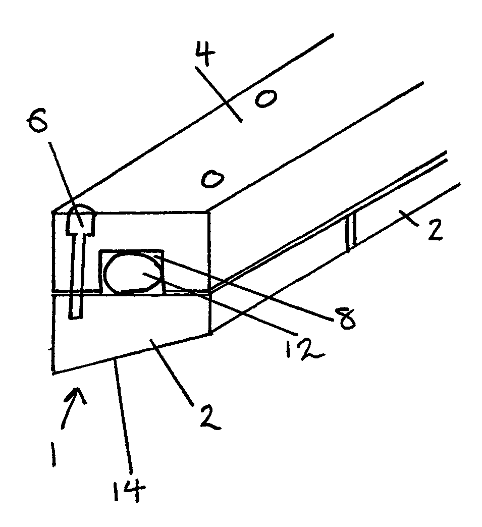
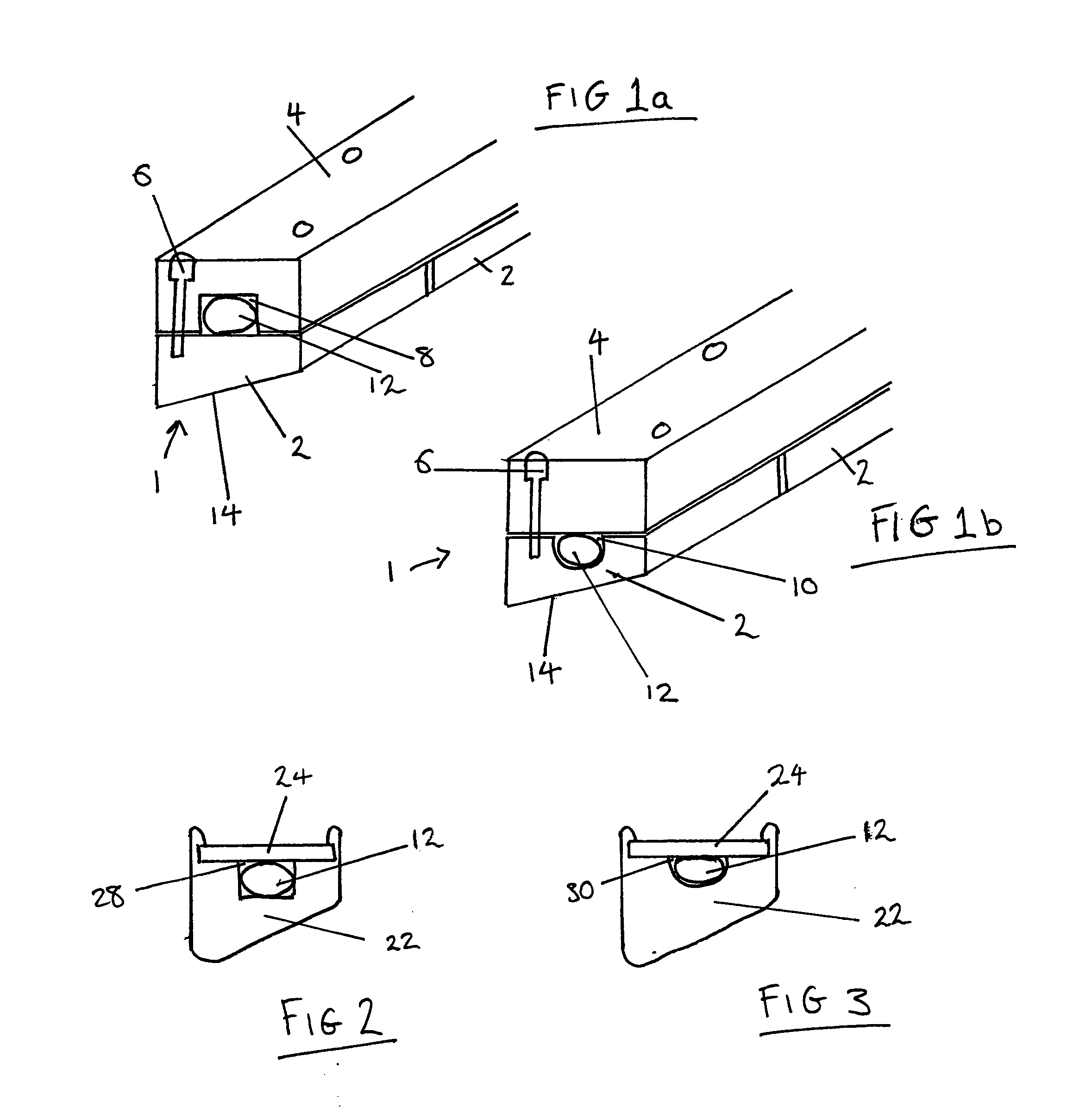
[0020]Referring to FIG. 1a, an anode 1 according to one embodiment of the invention comprises a plurality of thermally conductive anode segments 2 bolted to a rigid single piece support member in the form of a backbone 4 by bolts 6. A cooling channel 8, 10 extends along the length of the anode between the anode segments and the backbone and contains a coolant conduit in the form of a tube 12 arranged to carry the cooling fluid.

[0021]The anode segments 2 are formed from a metal such as copper and are held at a high voltage positive electrical potential with respect to an electron source. Each anode segment 2 has an angled front face 14, which is coated with a suitable target metal such as molybdenum, tungsten, silver or uranium selected to produce the required X-rays when electrons are incident upon it. This layer of target metal is applied to the front surface 14 using one of a number of methods including sputter coating, electro-deposition, chemical vapour deposition and flame spra...


PUM


Abstract

An anode for an X-ray tube includes at least one thermally conductive anode segment in contact with a rigid support member and cooling means arranged to cool the anode. The anode may further include a plurality of anode segments aligned end to end, each in contact with the support member.

Description

CROSS-REFERENCE TO RELATED APPLICATIONS[0001]The present application is a national stage application of PCT / GB2009 / 001760, filed on Jul. 15, 2009. The present application further relies on Great Britain Patent Application Number 0812864.7, filed on Jul. 15, 2008, for priority. Both priority applications are herein incorporated by reference in their entirety.FIELD OF THE INVENTION[0002]The present invention relates to X-ray tubes and in particular to the cooling of the anode of an X-ray tube.BACKGROUND OF THE INVENTION[0003]It is well known to provide an X-ray tube comprising an electron source and a metal anode, wherein the anode is at a positive potential with respect to the electron source. The electric field accelerates the emitted electron towards the anode. When they strike the anode they lose some, or all, of their kinetic energy, the majority of which is released as heat. This heat can reduce the target lifetime and it is therefore common to cool the anode. Conventional metho...

Claims


Application Information

Patent Timeline
Patent Type & Authority Applications(United States)
IPC IPC(8): H01J35/12
CPCH01J35/08H01J35/12H01J2235/081H01J2235/1262H01J2235/086H01J2235/1204H01J2235/083H01J35/13
Inventor MORTON, EDWARD JAMESLUGGAR, RUSSELL DAVIDHUNT, MARTIN
Owner RAPISCAN SYST INC (US)
Why Eureka
Try Eureka