Sealing Device for Steam Turbines and Method for Controlling Sealing Device

a sealing device and steam turbine technology, applied in the direction of machines/engines, mechanical devices, liquid fuel engines, etc., can solve the problems of increasing the amount not allowing for and avoiding the increase of steam leakage from the new clearance. , to achieve the effect of improving sealing performance, steam turbine efficiency and avoiding the increase of steam leakag

Inactive Publication Date: 2012-01-19
MITSUBISHI HITACHIPOWER SYST LTD
View PDF4 Cites 13 Cited by
  • Summary
  • Abstract
  • Description
  • Claims
  • Application Information

AI Technical Summary

Benefits of technology

[0018]The sealing device according to the present invention causes no dimensional increase in clearance due to free-cutting of an abradable material, avoids increases in the amount of steam leakage from clearances, and thus improves sealing performance and hence, steam turbine efficiency.

Problems solved by technology

However, arranging the fins and the abradable material to dimensionally minimize the clearances between the rotating region and the fixed region in an attempt to improve sealing performance causes free-cutting of the abradable material due to more frequent contact between the fins and the abradable material.
The increase in clearance due to free-cutting will, in turn, increase steam leakage from the new clearance.
The technique disclosed in JP-2002-228013-A does not allow for the increase in steam leakage from the new clearance formed by the free-cutting of the abradable material.
In addition, dimensionally increasing the clearance between the fins and the abradable material in order to prevent contact between both will dimensionally increase the clearances between the rotating region and the fixed region, and hence, steam leakage, thereby rendering it hopeless to improve steam turbine efficiency.

Method used


Image

  • Sealing Device for Steam Turbines and Method for Controlling Sealing Device
  • Sealing Device for Steam Turbines and Method for Controlling Sealing Device
  • Sealing Device for Steam Turbines and Method for Controlling Sealing Device

Examples


first embodiment

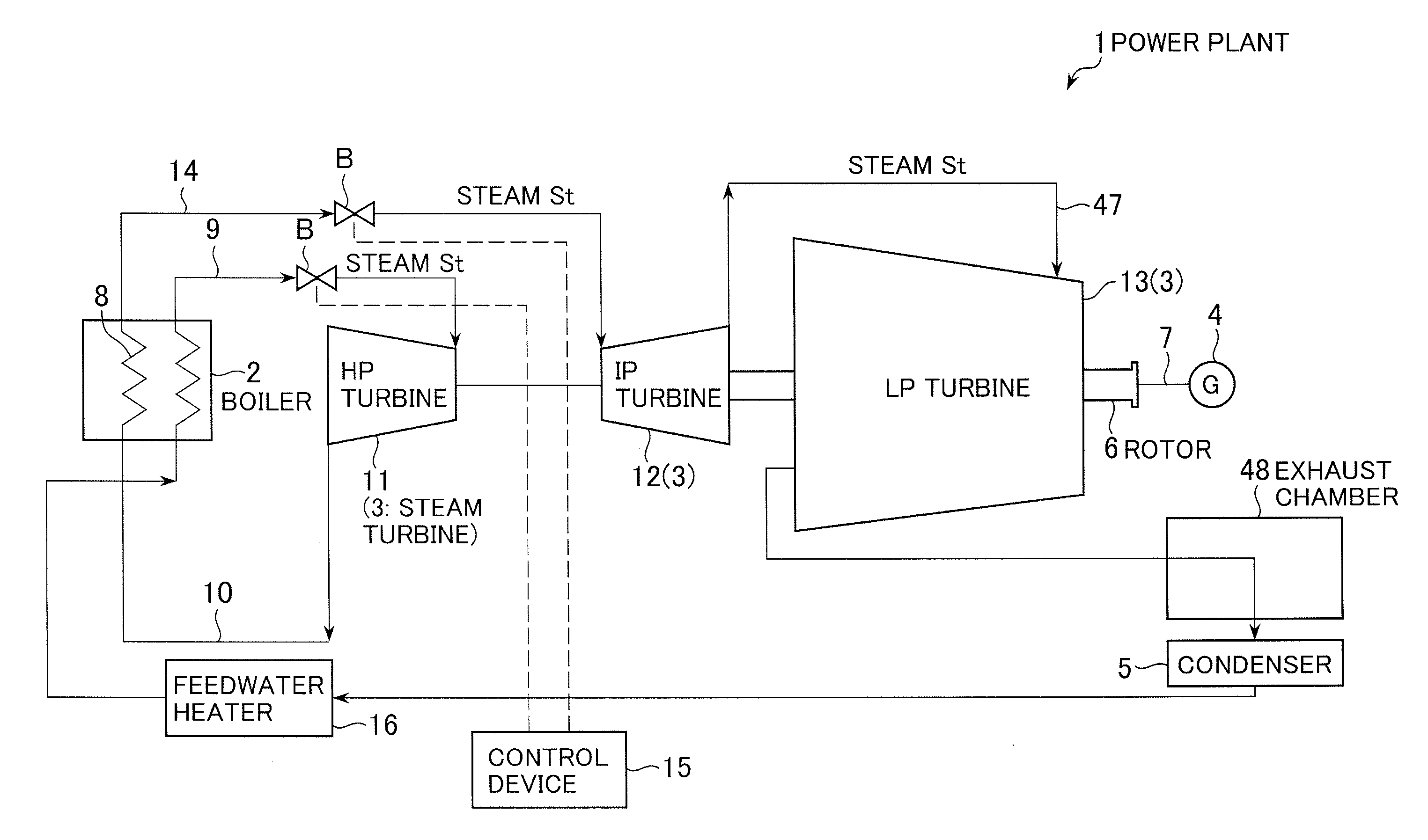
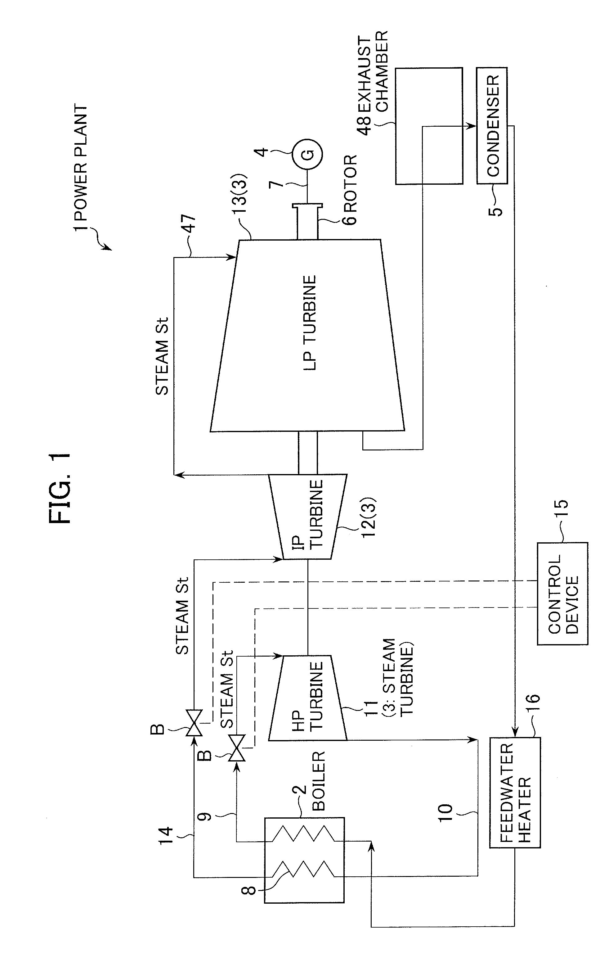
[0038]FIG. 1 is a systematic diagram showing schematically a power plant equipped with a steam turbine according to an embodiment of the present invention. As shown in FIG. 1, the power plant 1 includes a boiler 2, a steam turbine 3 (including a high-pressure turbine 11, an intermediate-pressure turbine 12, and a low-pressure turbine 13), a power generator 4, a condenser 5, and so on. The low-pressure turbine 13 has a rotor 6 coupled to a driving shaft 7 of the generator 4, which is then driven by rotation of the low-pressure turbine 13 to generate electric power.

[0039]The boiler 2 is a steam generator accommodating a reheater 8, and is connected to an inlet side of the high-pressure turbine 11 via a pipe 9. The high-pressure turbine 11 is connected at its outlet side to the reheater 8 of the boiler 2 via a pipe 10. The reheater 8 is connected to an inlet side of the intermediate-pressure turbine 12 via a pipe 14, and the intermediate-pressure turbine 12 is connected at its outlet s...

second embodiment

[0091]For example, the labyrinth sealing device 23 can be of a high-low type shown in FIG. 5, in addition to the shape shown in FIG. 3. The present invention can also be applied to the high-low type of labyrinth sealing device shown in FIG. 5.

[0092]In the present embodiment that FIG. 5 shows, free-cutting spacers 28 formed from a free-cutting metal are mounted between sealing fins 34 on a sealing base plate 25, and high portions 35 and low portions 36 of a rotor 18, as shown.

[0093]In addition, the sealing base plate 25 with the sealing fins 34 is mounted to be movable in an axial direction of the rotor 18.

[0094]The free-cutting metal that forms each free-cutting spacer 28 in the present invention is a highly workable (abradable) material. For example, if distal ends of the sealing fins 34 on the sealing base plate 25 and the free-cutting spacers 28 on the rotor 18 come into contact during rotor rotation, only the free-cutting spacers 28 are abraded and the sealing fins 34 remain und...

third embodiment

[0119]For example, the labyrinth sealing device 23 can be of a stagger type shown in FIG. 7, in addition to the shapes shown in FIGS. 3, 5. The present invention can also be applied to the stagger type of labyrinth sealing device shown in FIG. 7.

[0120]As shown in FIG. 7, a nozzle diaphragm inner ring 22 according to the present embodiment includes a sealing base plate 25 having a plurality of sealing fins 34.

[0121]The sealing base plate 25 is provided with a plurality of grooves 37 lined up at equal intervals in an axial direction of a rotor 18 and formed in a circumferential direction of the rotor, and one sealing fin 34 is fixed to each of the grooves 37 by caulking.

[0122]The rotor 18 is also provided with a plurality of grooves 38 lined up at equal intervals in the axial direction of the rotor 18 and formed in a circumferential direction of the rotor, and one sealing fin 24 is fixed to each of the grooves 38 by caulking.

[0123]The sealing fins 34 on the sealing base plate 25 and t...


PUM


Abstract

Subject: To provide a sealing structure, and control method therefor, which improve sealing performance between a rotating region and a fixed region, prevent fins from being damaged, and prevent increases in the amount of steam leakage from any clearances newly formed by further abrasion of an abradable material.
Solution: The sealing structure in which free-cutting spacers 28 on a sealing base plate 25 and sealing fins 24 on a rotor 18 are opposed to each other is provided, in the sealing structure of which the sealing base plate 25 is disposed so as to be movable in an axial direction of the rotor 18. When a steam turbine 3 increases in load, a pressure head 30 moves in an axial steam-pressure loading direction of the rotor 18 and the sealing base plate 25 connected to the pressure head 30 moves in the axial steam-pressure loading direction. Since the free-cutting spacers 28 at positions opposed to those of the sealing fins 24 existing after the movement of the sealing base plate are maintained in a non-contact state, clearances between the sealing fins 24 and the free-cutting spacers 28 are dimensionally minimized.

Description

BACKGROUND OF THE INVENTION[0001]1. Field of the Invention[0002]The present invention relates to a sealing device for steam turbines.[0003]2. Description of the Related Art[0004]Power-generating plants that generate electric power by rotating steam turbines with the steam generated by boilers or the like are commonly equipped with, in order from the upstream side of the flow of the steam, high-pressure turbines, intermediate-pressure turbines, and low-pressure turbines, as the steam turbines. The steam that has been used to rotate a low-pressure turbine is introduced into a condenser via an exhaust hood and then condensed by the condenser to become feedwater. The feedwater is recycled into the steam generator.[0005]In the steam turbines constituting such a power plant, stationary blades fixed to the inside of a casing are arranged between the moving blades that rotate integrally with a rotor, and stages including the stationary blades and the moving blades are formed.[0006]The steam...

Claims


Application Information

Patent Timeline
Patent Type & Authority Applications(United States)
IPC IPC(8): F01D11/02
CPCF01D11/06F01D11/22F05D2220/31F16J15/445F16J15/442
Inventor NARITA, KENJIROYAMAZAKI, HARUYUKIKUDO, TAKESHIMURATA, KENICHI
Owner MITSUBISHI HITACHIPOWER SYST LTD
Why Eureka
Try Eureka