Method for Purging Fuel Vapors

a technology of fuel vapor and purging method, which is applied in the direction of combustion air/fuel air treatment, electric control, instruments, etc., can solve the problems of insufficient purging of fuel vapor from fuel vapor storage canisters, insufficient purging of fuel vapor from intake manifolds, and inability to reduce engine displacement, so as to increase engine efficiency, boost the engine, and reduce the effect of engine displacemen

Active Publication Date: 2012-01-19
FORD GLOBAL TECH LLC
View PDF0 Cites 41 Cited by
  • Summary
  • Abstract
  • Description
  • Claims
  • Application Information

AI Technical Summary

Benefits of technology

[0002]One way to increase engine efficiency is to reduce engine displacement and boost the engine. Lowering the engine displacement can reduce engine pumping work and friction, thereby increasing engine efficiency. Further, boosting

Problems solved by technology

However, downsizing and boosting an engine can also have drawbacks.
For example, it may be more difficult to purge fuel vapors from a fuel vapor storage canister when an engine is boosted by a turbocharger or supercharger.
In particular, during some operating conditions intake manifold pressure may be too high to create a desired am

Method used


Image

  • Method for Purging Fuel Vapors
  • Method for Purging Fuel Vapors
  • Method for Purging Fuel Vapors

Examples


Embodiment Construction

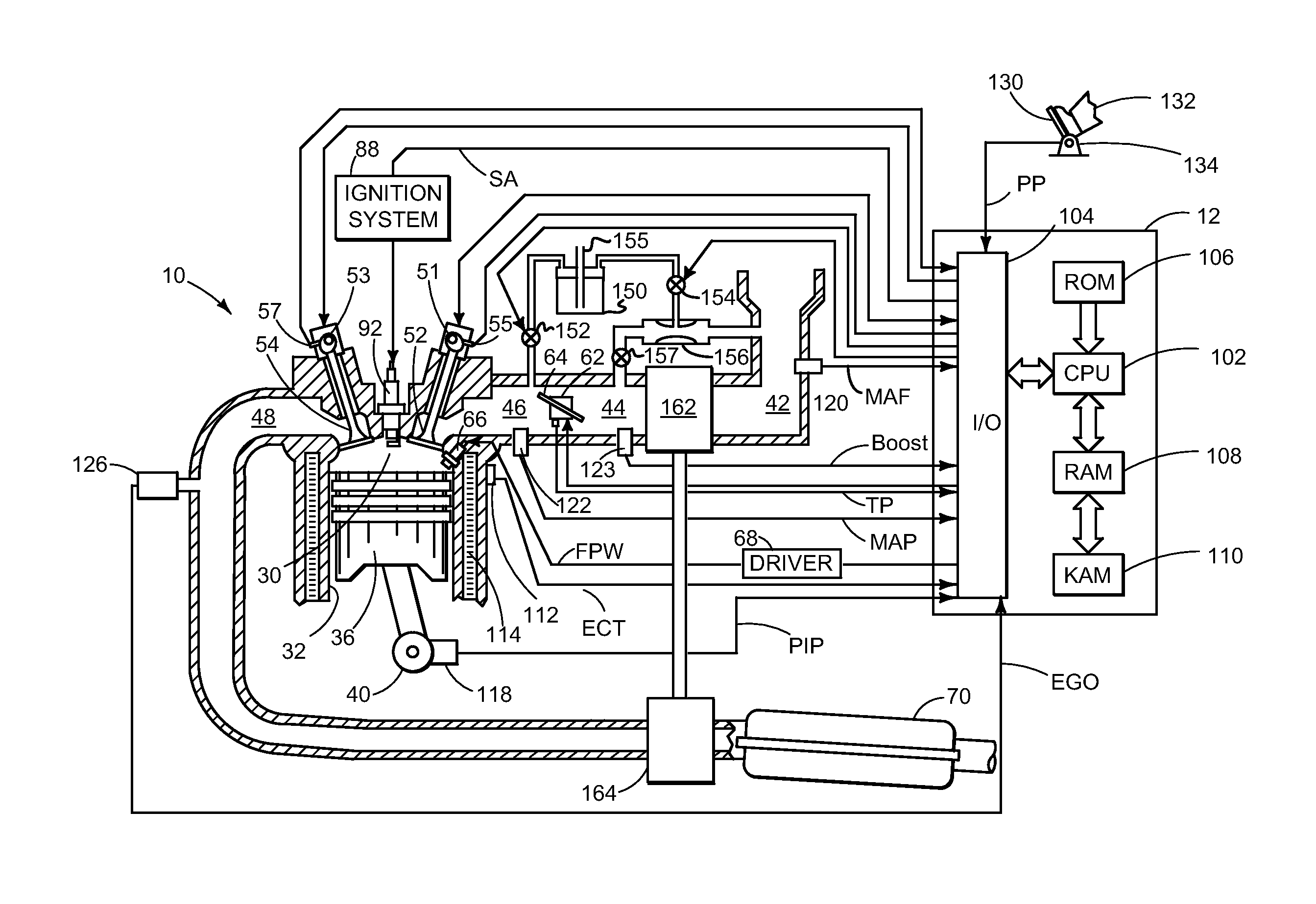
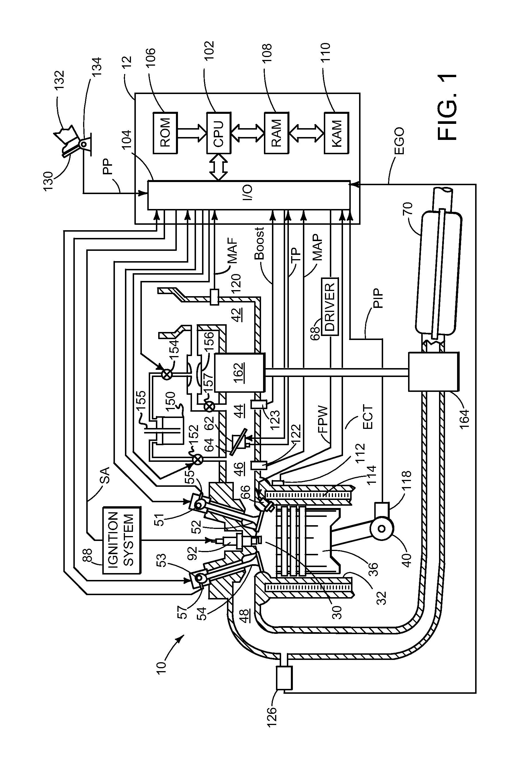
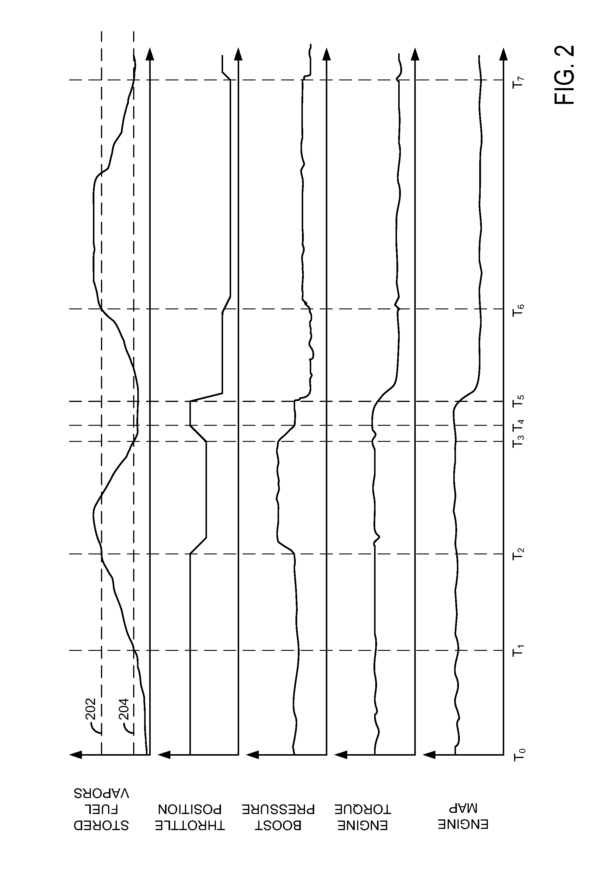
[0015]The present description is related to purging fuel vapors from a boosted engine. In one non-limiting example, the engine may be configured as illustrated in FIG. 1 with a turbocharger for boosting the air amount supplied to the engine. In one example, the turbocharged engine system is operated according to the methods of FIGS. 4-5 providing the signals of FIGS. 2-3.

[0016]Referring to FIG. 1, internal combustion engine 10, comprising a plurality of cylinders, one cylinder of which is shown in FIG. 1, is controlled by electronic engine controller 12. Engine 10 includes combustion chamber 30 and cylinder walls 32 with piston 36 positioned therein and connected to crankshaft 40. Combustion chamber 30 is shown communicating with intake manifold 46 and exhaust manifold 48 via respective intake valve 52 and exhaust valve 54. Each intake and exhaust valve may be operated by an intake cam 51 and an exhaust cam 53. Alternatively, one or more of the intake and exhaust valves may be opera...


PUM


Abstract

A method for improving purging of fuel vapors from a boosted engine is presented. In one embodiment, the method increases the efficiency of a venturi that supplies vacuum to purge fuel vapors from a vapor storage canister.

Description

FIELD[0001]The present description relates to a method for improving the purging of fuel vapors from a fuel vapor canister. The method may be particularly useful for purging fuel vapors when intake manifold pressure is higher than a threshold amount.BACKGROUND AND SUMMARY[0002]One way to increase engine efficiency is to reduce engine displacement and boost the engine. Lowering the engine displacement can reduce engine pumping work and friction, thereby increasing engine efficiency. Further, boosting can increase the engine output so that a smaller boosted engine can produce power that is similar to a larger displacement normally aspirated engine. In this way, engine efficiency can be increased while engine output is maintained.[0003]However, downsizing and boosting an engine can also have drawbacks. For example, it may be more difficult to purge fuel vapors from a fuel vapor storage canister when an engine is boosted by a turbocharger or supercharger. In particular, during some oper...

Claims


Application Information

Patent Timeline
IPC IPC(8): F02D41/00F02M33/02
CPCF02D37/02F02D41/0007Y02T10/144F02M25/08F02D41/003Y02T10/12
Inventor CUNNINGHAM, RALPH WAYNEPETERS, MARK
Owner FORD GLOBAL TECH LLC
Why Eureka
Try Eureka