
Cream solder and method of soldering electronic part

a soldering electronic and cream technology, applied in the field of cream soldering and soldering electronic parts, can solve the problems of undetectable need for reducing atmosphere for organic materials, no practical solder materials that can be used widely, etc., and achieve good bonding properties and high strength and thermal stability

Active Publication Date: 2012-01-26
NIHON HANDA +1
View PDF1 Cites 29 Cited by
  • Summary
  • Abstract
  • Description
  • Claims
  • Application Information

AI Technical Summary

Benefits of technology

[0019]The present invention has been made under the above circumstances, and aims as an object thereof at providing a high-temperature lead-free solder material which is based on an inexpensive Sn—Ag—Cu solder alloy having high strength and thermal stability and good bonding property, and is suitable for application to dual-temperature solder connection, and a method of soldering an electronic part.
[0020]The present invention also aims as another object thereof at providing a high-temperature lead-free solder material which can form a solder joint of improved heat resistance and reliability, and is suitable for application to dual-temperature solder connection, and a method of soldering an electronic part.

Problems solved by technology

Although an Au-Sn alloy (having a eutectic melting point of 280° C.) is available as a high-temperature lead-free solder material which can be used for dual-temperature solder connection, it is expensive and there is no practical solder material that can be used widely.
Therefore, they undesirably require a reducing atmosphere for the organic material, the application of a load, etc. to be capable of functioning as a joining material.

Method used


Image

  • Cream solder and method of soldering electronic part
  • Cream solder and method of soldering electronic part
  • Cream solder and method of soldering electronic part

Examples


Embodiment Construction

First Invention

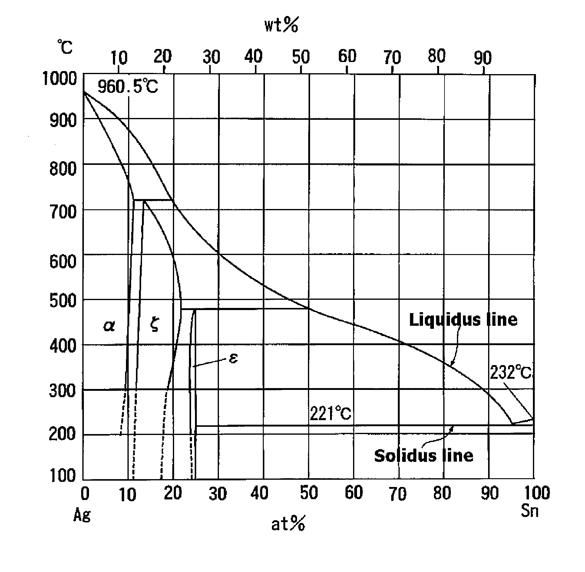
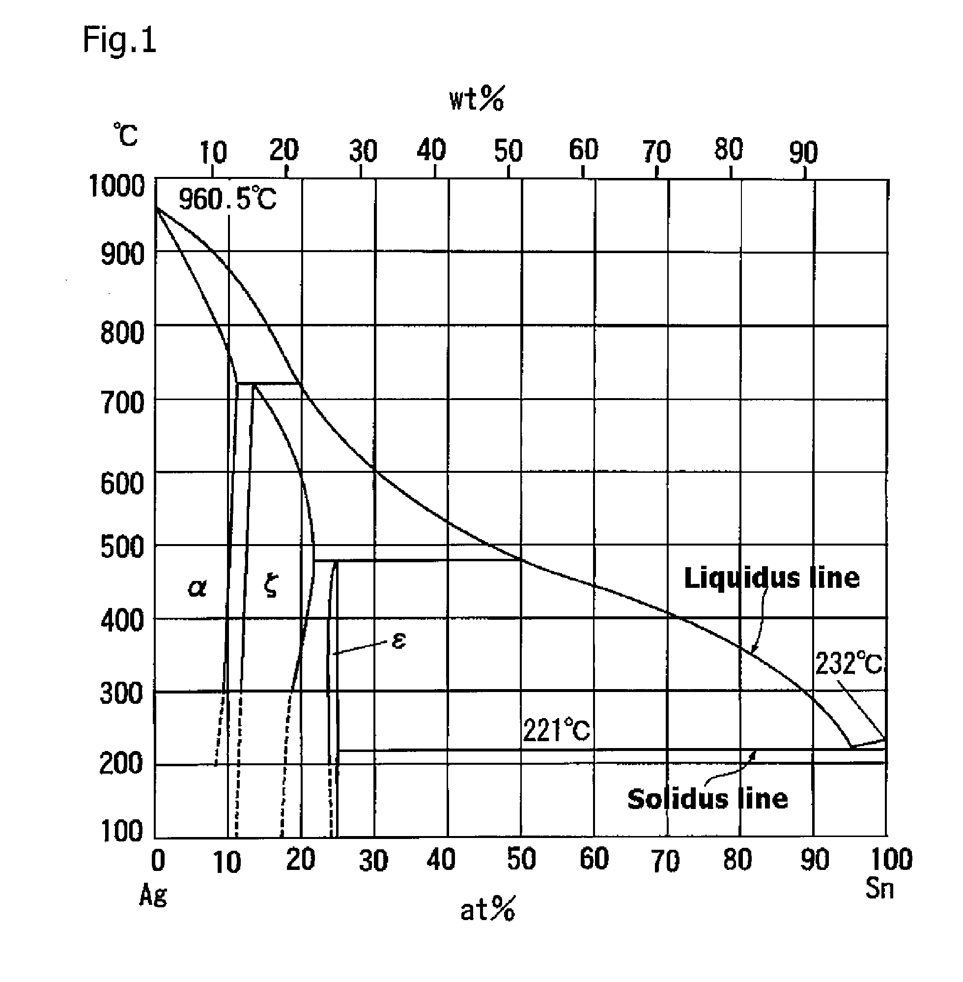
[0047]Description will now be made of a specific form of the first invention with reference to the Sn—Ag phase diagram shown as FIG. 1. Specific examples of the solder cream according to the first invention, the results of their evaluation, etc. will be described later in the section of Examples.

[0048]The following description employs a simplified expression of a composition for convenience of explanation. For example, 3.5 wt % Ag is indicated as 3.5% Ag or Ag3.5%, or more simply as 3.5Ag.

[0049]Reference is first made to the Sn—Ag phase diagram in FIG. 1. In FIG. 1, the vertical axis shows temperatures, degree centigrade (° C.) and the horizontal axis shows the proportion of Sn in atomic % (at %) at bottom and in weight % (wt %) at top. In the phase diagram in FIG. 1, the liquidus line is a line showing the temperature at which a solid phase begins to crystallize from a complete liquid on congelation, or at which a solid turns into a complete liquid on heating. The so...


PUM

PropertyMeasurementUnit
melting pointaaaaaaaaaa
temperatureaaaaaaaaaa
melting pointaaaaaaaaaa

Abstract

A cream solder obtained by kneading an Sn—Ag—Cu alloy together with a flux, wherein the Sn—Ag—Cu alloy includes a mixture of a first powdery alloy and a second powdery alloy, the first powdery alloy is represented by an Sn—Ag phase diagram having a solid-liquid coexistence region and has a given silver amount which is larger than that in the eutectic composition (3.5 wt. % silver), and the second powdery alloy has a silver amount which is that in the eutectic composition (3.5 wt. % silver) or which is close to that in the eutectic composition and is smaller than that in the first powdery alloy. This cream solder has excellent strength and thermal stability, and satisfactory bonding properties. It is based on an inexpensive Sn—Ag—Cu solder alloy. It is suitable for use as a high-temperature-side lead-free solder material conformable to temperature gradation bonding. Also provided is a method of soldering.

Description

TECHNICAL FIELD[0001]The present invention relates to a solder cream used for soldering electronic parts, particularly a solder cream formed from a solder alloy for the high-temperature side of dual-temperature solder connection which is a lead-free solder alloy not containing lead, and a method of soldering electronic parts.BACKGROUND ART[0002]The reflow process is usually employed for soldering an electronic part to a printed circuit board, or the like. The reflow process is a process for soldering an electronic part to a printed circuit board by applying a solder cream to an area of the printed circuit board to which the electronic part is to be soldered, mounting the electronic part so that its electrode and planar lead may engage the applied area, and heating the printed circuit board in a ref low oven to melt the solder cream.[0003]The solder cream used in the ref low process is a viscous solder material obtained by kneading a solder alloy powder and a flux paste. The solder a...

Claims


Application Information

Patent Timeline
Patent Type & Authority Applications(United States)
IPC IPC(8): B23K35/26
CPCB23K1/0016B23K35/0244H01L2924/0133H01L2924/0132H05K2201/0272H05K2201/0266H05K3/3484C22C28/00B23K35/025B23K35/262B23K2201/36B23K2201/42C22C1/0483C22C12/00C22C13/00H01L2924/01047H01L2924/0105H01L2924/01029B23K2101/36B23K2101/42H05K3/3485B23K35/26B23K1/00H05K3/34H05K3/341H05K2203/04H05K2203/12
Inventor YAMASHITA, MITSUOGOTO, TOMOAKIASAGI, TAKESHI
Owner NIHON HANDA
Learn More