Power Tool Having An Electric Brake

Active Publication Date: 2012-01-26
C & E FEIN
View PDF14 Cites 33 Cited by
  • Summary
  • Abstract
  • Description
  • Claims
  • Application Information

AI Technical Summary

Benefits of technology

[0057]The detection of the drive rotational speed or of the drive speed or of a variable characterizing these may be used, in combination with the detection of the switch-on state of the power tool, to ascertain what is known as an overrun and shorten it by means of a braking action. Power tools rotating at high speed with high kinetic energy or with high inertia in the drive often take a long time to slow down, even after being switched off, before the tool comes to a standstill. This may be the case, for example, with regard to angle grinders. An operator should therefore hold or guide the power tool in a controlled manner for some time even after immediate switch-off, wait for the tool standstill and put down the tool only thereafter, so that uncontrollable operating states or intrinsic movements can be avoided. By means of an adapted braking procedure, an overrun brake can be implemented and the time until the tool standstill can be markedly shortened.
[0058]Finally, the operating temperature of the power tool, for example of a gear or of the motor, can be monitored, so that high loads or overlo

Problems solved by technology

However, rapid deceleration may also be necessary when an inadmissible operating state is recognized, for example excessive twisting of the power tool on account of a high moment of reaction if the tool is jammed A decelerating action may also serve for quickly braking a tool taking relatively lon

Method used


Image

  • Power Tool Having An Electric Brake
  • Power Tool Having An Electric Brake
  • Power Tool Having An Electric Brake

Examples


Example

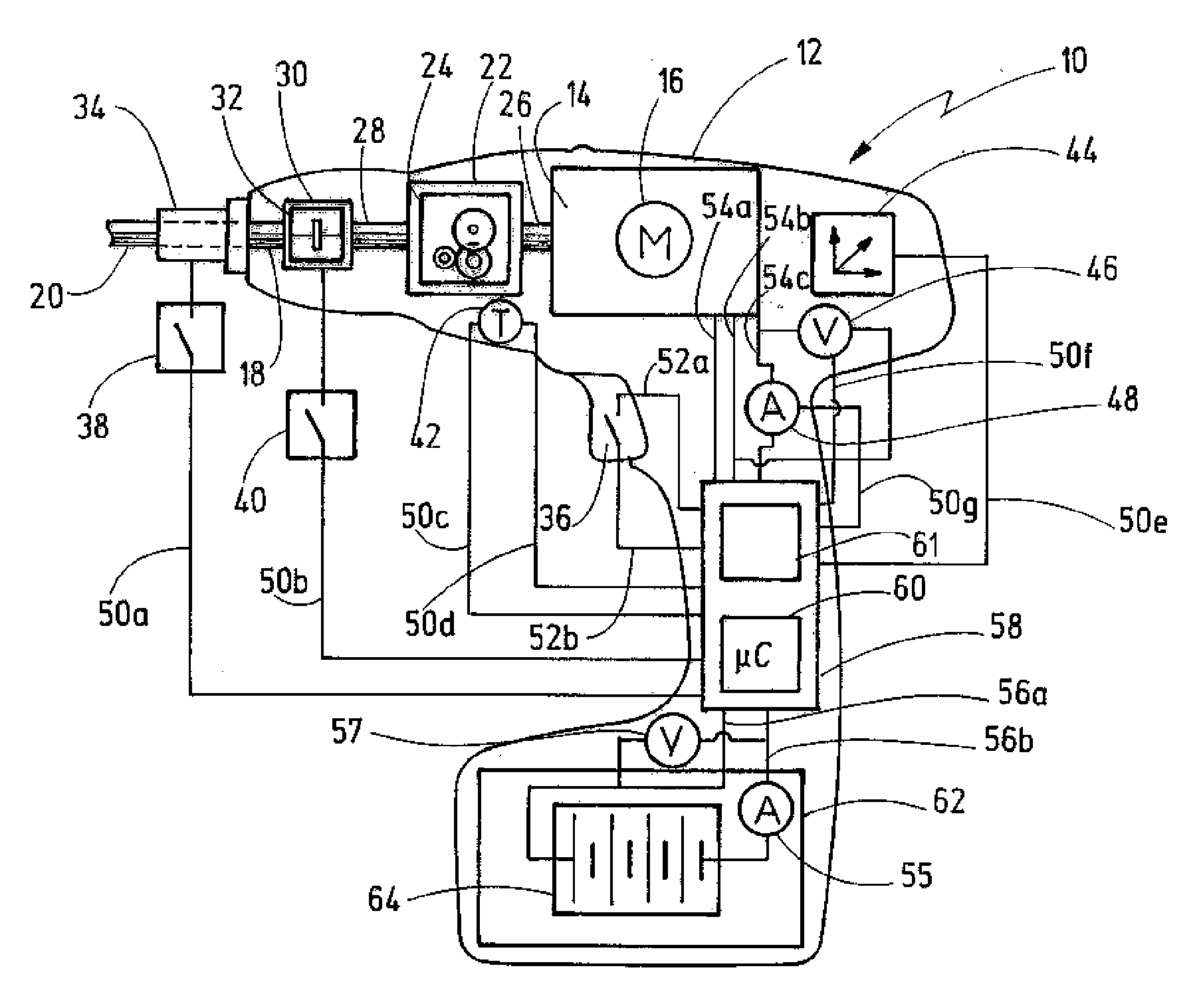
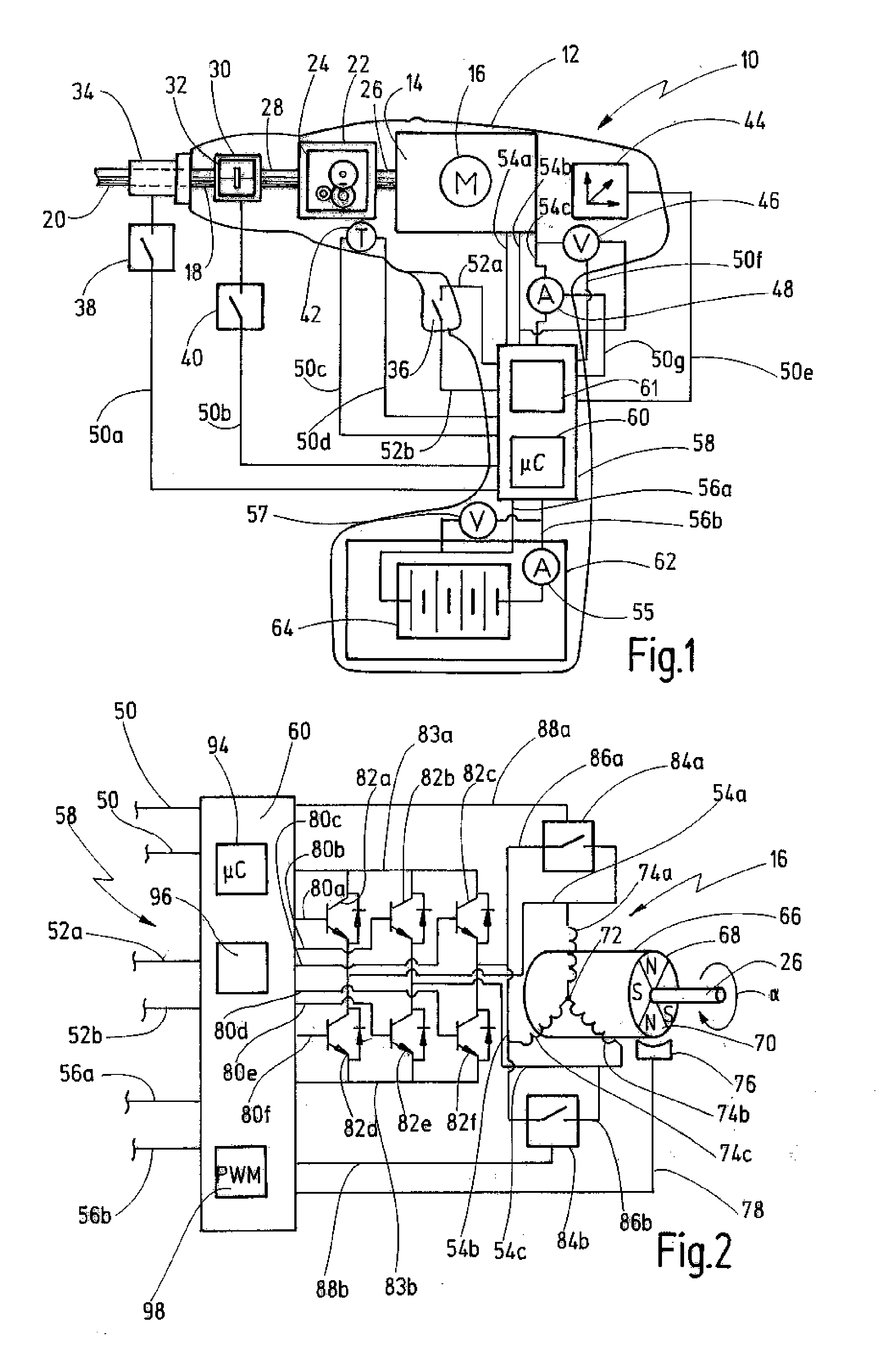
[0098]A power tool according to the invention is illustrated diagrammatically in simplified form and designated as a whole by 10 in FIG. 1.

[0099]The power tool 10 has a housing 12 which receives a drive 14 with a motor 16. The drive 14 is coupled to a tool 20 (not illustrated in full) via a drive 18. Furthermore, a transmission device 22, in the present case comprising a gear 24, a motor shaft 26, a gear shaft 28 and an engagement device 30, in the present case comprising a clutch 32, are interposed between the drive 14 and the drive 18.

[0100]The power tool 10 is illustrated in FIG. 1, by way of example, as a screwing tool or as a drilling tool. It will be appreciated, however, that it could also be a tool for grinding, polishing, sawing, cutting, hammering or the like which can be provided with the same or similar components.

[0101]It should be noted, furthermore, that the illustration according to FIG. 1 illustrates a possible maximum configuration of the power tool 10, on the basi...


PUM


Abstract

The invention relates to a method for decelerating a drive movement of a power tool and to a power tool suitable for carrying out the method, having a drive driven by a motor, an energy supply device for the provision of electrical energy, a controller having a motor controller for activating the motor and an operating-state recognition module which is to detect at least one operating-state variable and, as a function of this, to output a brake signal, the controller being designed to initiate, as a function of the brake signal, a braking procedure in which brake cycles are provided which have a first time segment, in which the motor is short-circuited, and a second time segment in which current is fed to the motor opposite to its original direction of rotation.

Description

CROSS-REFERENCES TO RELATED APPLICATIONS[0001]This invention claims Convention Priority of German patent application Serial No. 10 2010 032 335.7 filed on Jul. 20, 2010, the entire contents of which is full incorporated herein by reference.BACKGROUND OF THE INVENTION[0002]The invention relates to a power tool comprising a motor which is couplable to a drive, an energy supply device for the provision of electric energy, a controller having a motor controller for activating the motor, and further comprising an operating-state recognition module which is configured to detect at least one operating-state variable and, as a function of this, to output a brake signal.[0003]The subject of the invention is, furthermore, a method for decelerating a drive movement of a power tool.[0004]A power tool of this type is known from DE 10 2008 033 866 A1.[0005]The known power tool is a machine tool with a controller having a limitation device for limiting an output torque provided on the drive side. ...

Claims


Application Information

Patent Timeline
IPC IPC(8): H02P3/12H02P3/10
CPCB25F5/001H02P3/20H02P2209/07H02P6/24H02P3/22
Inventor KAUFMANN, MICHAELRINCKLEB, ULF
Owner C & E FEIN
Why Eureka
Try Eureka