A slag separation component and a circulating fluidized bed incinerator using the component

A technology of circulating fluidized bed and separation components, which is applied in the direction of incinerator, combustion method, combustion type, etc., and can solve the problems of relatively strict operating environment requirements, secondary pollution of the surrounding environment, and waste of heat, so as to avoid the difficulty of furnace temperature rise, Guarantee the effect of working intensity requirements and high constant temperature requirements

Active Publication Date: 2016-08-31
南通欣源污泥处置科技有限公司
View PDF6 Cites 0 Cited by
  • Summary
  • Abstract
  • Description
  • Claims
  • Application Information

AI Technical Summary

Problems solved by technology

[0003] The above-mentioned incinerator structure, the temperature in the incineration chamber used to incinerate domestic waste needs to reach a high temperature of at least 800 degrees Celsius, and the flue gas stays in the incineration chamber for about 3 seconds, in order to be beneficial to achieve the purpose of pyrolysis of dioxins and various harmful gases ; and because of the low calorific value of the current domestic waste due to moisture problems, coupled with the water wall pipes arranged in the incineration chamber, it often causes a reduction in the combustion temperature in the incineration chamber, which is not only difficult to meet the requirements of the hot dry steam of the external steam turbine unit At the same time, the burned gas finally discharged from the furnace contains a large amount of harmful substances such as dioxins, which will cause secondary pollution to the surrounding environment
Nowadays, some manufacturers are trying to increase the inherent combustion temperature in the incineration chamber by removing the water-cooled wall in the square incineration chamber and only arranging the water-cooled wall in the flue for water heating; however, due to the current furnace structure of the incineration chamber Features, the water-cooled wall is not only used as a heating carrier for water, but also as a load-bearing carrier for the heat-insulating refractory mud on the furnace body. The heat-insulating refractory mud will not collapse under the double clamping of the inner water-cooled wall and the outer furnace shell. Once taken out How to ensure the normal operation of the entire square furnace body without collapsing becomes a difficult problem for the water-cooled wall
There are also some manufacturers who attach the heat-insulating refractory mud by nailing the steel threaded bars into the heat-insulating refractory mud, so as to realize the heat-insulation performance of the refractory mud for the furnace body. At the same time as refractory mud, it also becomes a heat conductor, so that it is easy to conduct the high temperature accumulated in the incineration chamber; on the other hand, refractory mud has strict requirements on its use environment. Mud is often accompanied by dilution and crisping during use, requiring frequent manual maintenance; in addition, there are also problems with the setting of the cyclone separator as a gas-solid separator. The traditional circulating fluidized bed incinerator unit still uses hot air extraction Utilize heat energy, and return the separated solid slag to the main incineration chamber or directly discharge it according to the situation, regardless of the so-called "depending on the situation" brought by the cumbersome operation and the requirements for the operator's operating experience In terms of high-temperature solid slag, if it needs to be discharged and finally led to the external atmosphere, it must go through a large number of forced cooling processes such as direct water cooling, which consumes a lot of resources and high operating costs. Huge heat, which brings great troubles to on-site operators and incineration operators

Method used


Image

  • A slag separation component and a circulating fluidized bed incinerator using the component
  • A slag separation component and a circulating fluidized bed incinerator using the component
  • A slag separation component and a circulating fluidized bed incinerator using the component

Examples


Embodiment Construction

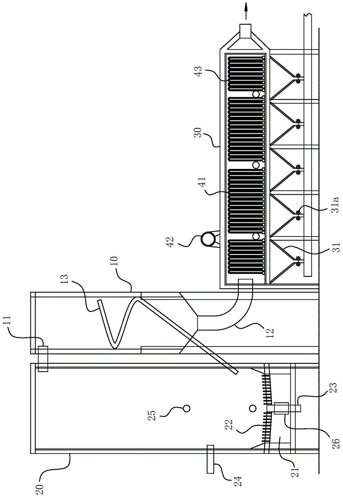
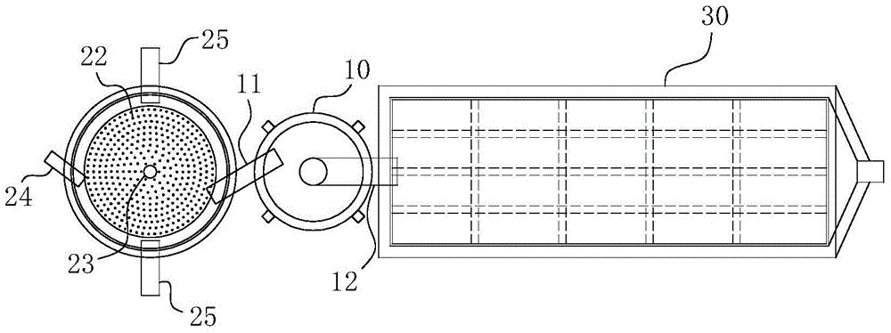
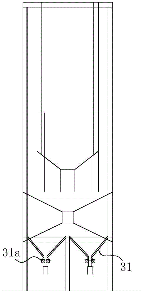
[0038] For ease of understanding, combined here Figure 1-5 Specifically set forth the component structure of the present invention and its specific work flow:

[0039] Concrete structure of the present invention can refer to Figure 1-5 As shown, it includes a basic frame part and a cylindrical main incineration chamber 20 arranged on the frame part for incinerating garbage. The main incineration chamber 20 includes an outer furnace shell 20a arranged from outside to inside, a furnace body insulation cotton Layer 20b, inner furnace shell layer 20c, and furnace body refractory brick layer 20d. The slag separation assembly for automatic slag separation and the burnt-out slag ash discharged from the slag separation assembly are arranged in sequence on the side of the main incineration chamber 20. The flue 30 for heat energy utilization, after high-temperature incineration in the main incineration chamber 20 generates high-temperature hot gas, the high-temperature hot gas mixed ...


PUM


Abstract

The invention belongs to the field of garbage incineration equipment, and particularly relates to a furnace slag separation assembly and a circulating sulfuration bed incinerator using the assembly. The furnace slag separation assembly comprises a cylinder, wherein the cylinder is provided with a feed inlet, and the bottom of the cylinder is provided with a discharge port; the side wall of the cylinder is provided with spiral grooves from top to bottom in a concave mode and / or provided with spiral guide rails in a convex mode along the axis of the side wall of the cylinder. The circulating sulfuration bed incinerator using the furnace slag separation assembly at least comprises a main incineration chamber and a flue, a heat energy utilization assembly is arranged on the flue, and the furnace slag separation assembly is clamped between the main incineration chamber and the flue, and the outlet ends of the spiral grooves and / or the spiral guide rails are communicated with a furnace cavity of the main incineration chamber. The treatment mode is intelligent and quick, the effects of efficiently sorting and treating unburned furnace slag are automatically achieved, and meanwhile, labor intensity of operators is effectively lowered. The furnace slag separation effect of the assembly is achieved, and meanwhile, work reliability and efficiency of an incinerator body of the incinerator are effectively guaranteed.

Description

technical field [0001] The invention belongs to the field of garbage incineration equipment, in particular to a slag separation component and a circulating fluidized bed incinerator using the component. Background technique [0002] In the circulating fluidized bed incinerator unit, the combustion system (that is, the material circulation system) is usually composed of the incineration chamber, the gas-solid separator and other equipment; the water wall, the superheater, the economizer, the air preheater and the tail flue It constitutes the heat exchange and transmission system of the incinerator; the flue gas purification system of the incinerator is composed of dust collectors; the wind energy of the fan is used to drive the wind energy of the fan as its serial cycle power. In actual operation, the waste is burned in the incineration chamber of the incinerator, and the heat energy generated by it is absorbed by many heat exchange components such as the water cooling wall o...

Claims


Application Information

Patent Timeline
Patent Type & Authority Patents(China)
IPC IPC(8): F23G5/44
Inventor 李登平韩莹
Owner 南通欣源污泥处置科技有限公司
Why Eureka
Try Eureka