Capacitive touch panel

a capacitive touch and touch panel technology, applied in the direction of resistive/reacting/impedence, pulse technique, instruments, etc., can solve the problems of complex circuit configuration, increased size, and inability to detect input operations made to sensing electrodes in a short tim

Inactive Publication Date: 2012-01-26
SMK CORP
View PDF1 Cites 11 Cited by
  • Summary
  • Abstract
  • Description
  • Claims
  • Application Information

AI Technical Summary

Benefits of technology

[0029]The gradient of change of the voltage of sensing electrodes differs between when the stray capacitance is charged and when the stray capacitance is discharged according to elapsed time from the base point in time. This makes it possible to select either the charge or discharge control of the stray capacitance according to the threshold potential to make the gradient of the electric potential of the sensing electrode smaller

Problems solved by technology

This results in a longer scanning cycle during which the crossing points of respective electrodes are scanned, making it impossible to detect an input position in a short time.
There is the problem in that the circuit configuration is complicated and increased in size.
This makes it quite difficult to detect an input operation made to a sensing electrode directly from comparison of charging times or discharging times until a threshold potential is achieved.
However, this in turn generates the condition of a high impedance close to an insulated condition to cause flow of a sensing current in a microcomp

Method used


Image

  • Capacitive touch panel
  • Capacitive touch panel
  • Capacitive touch panel

Examples


Embodiment Construction

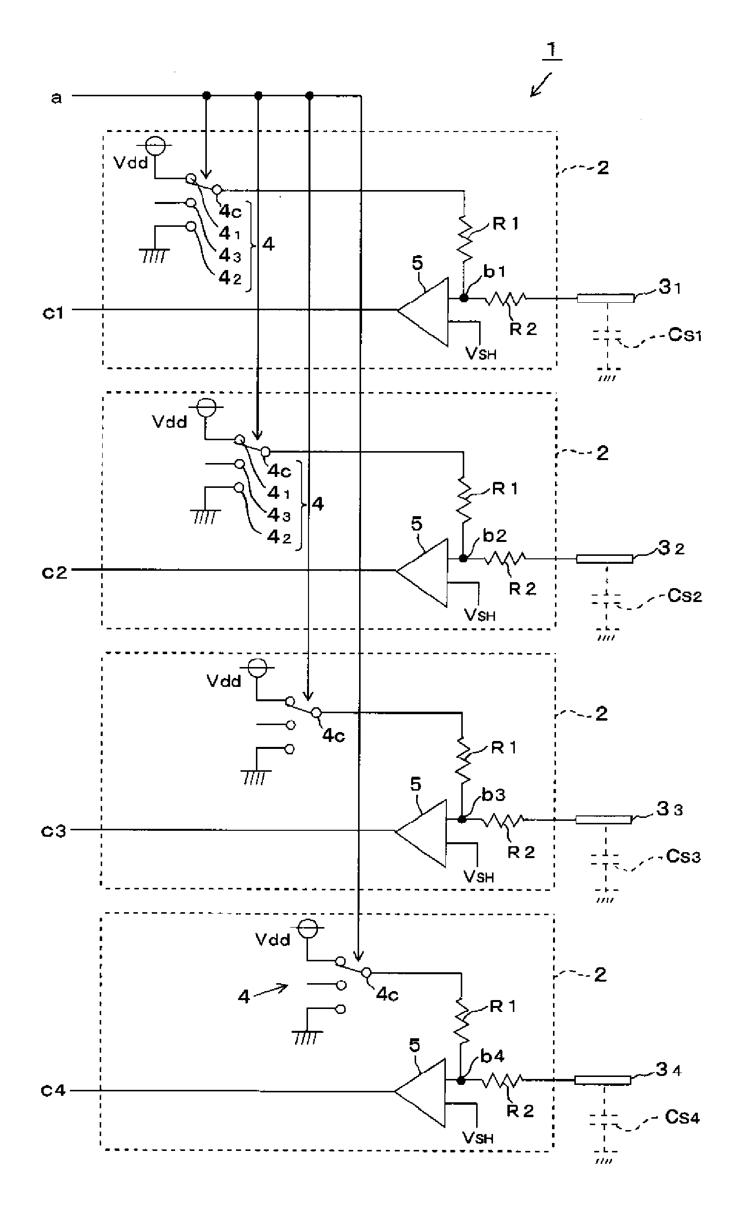
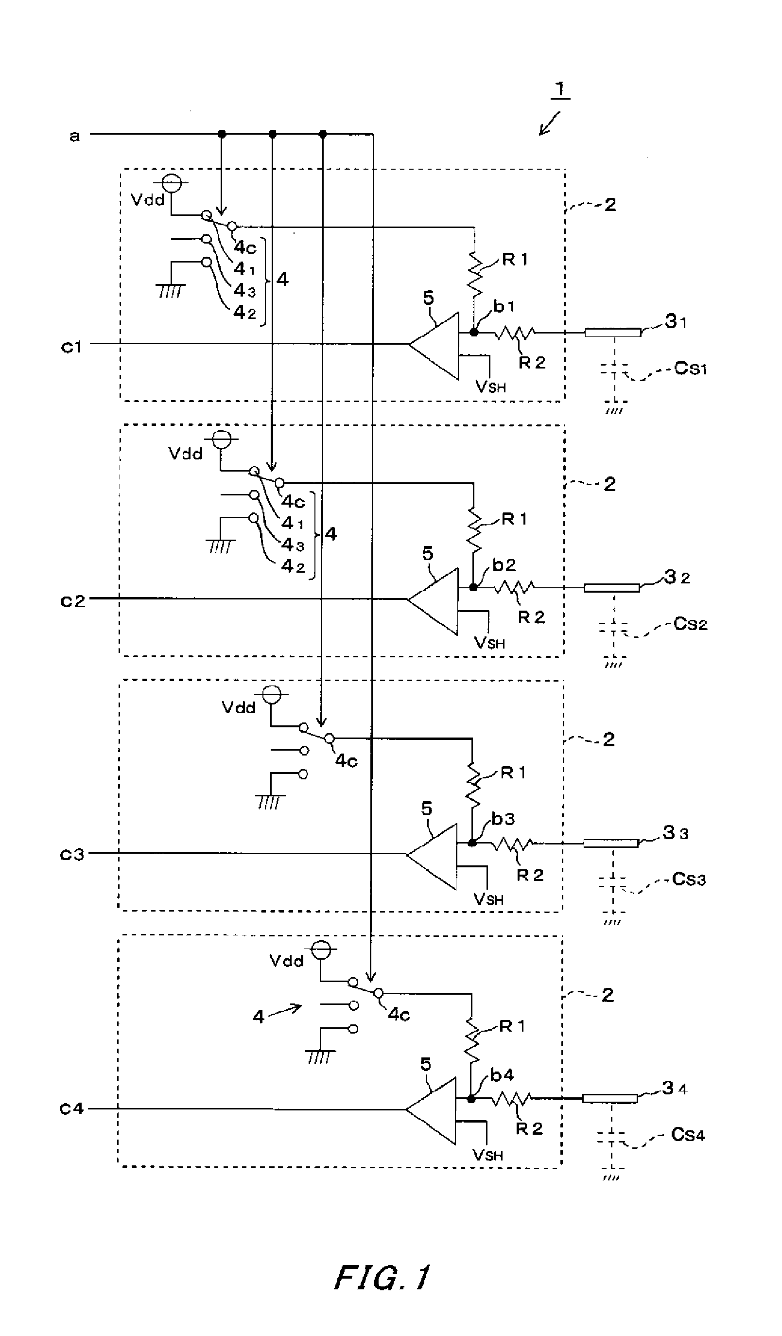
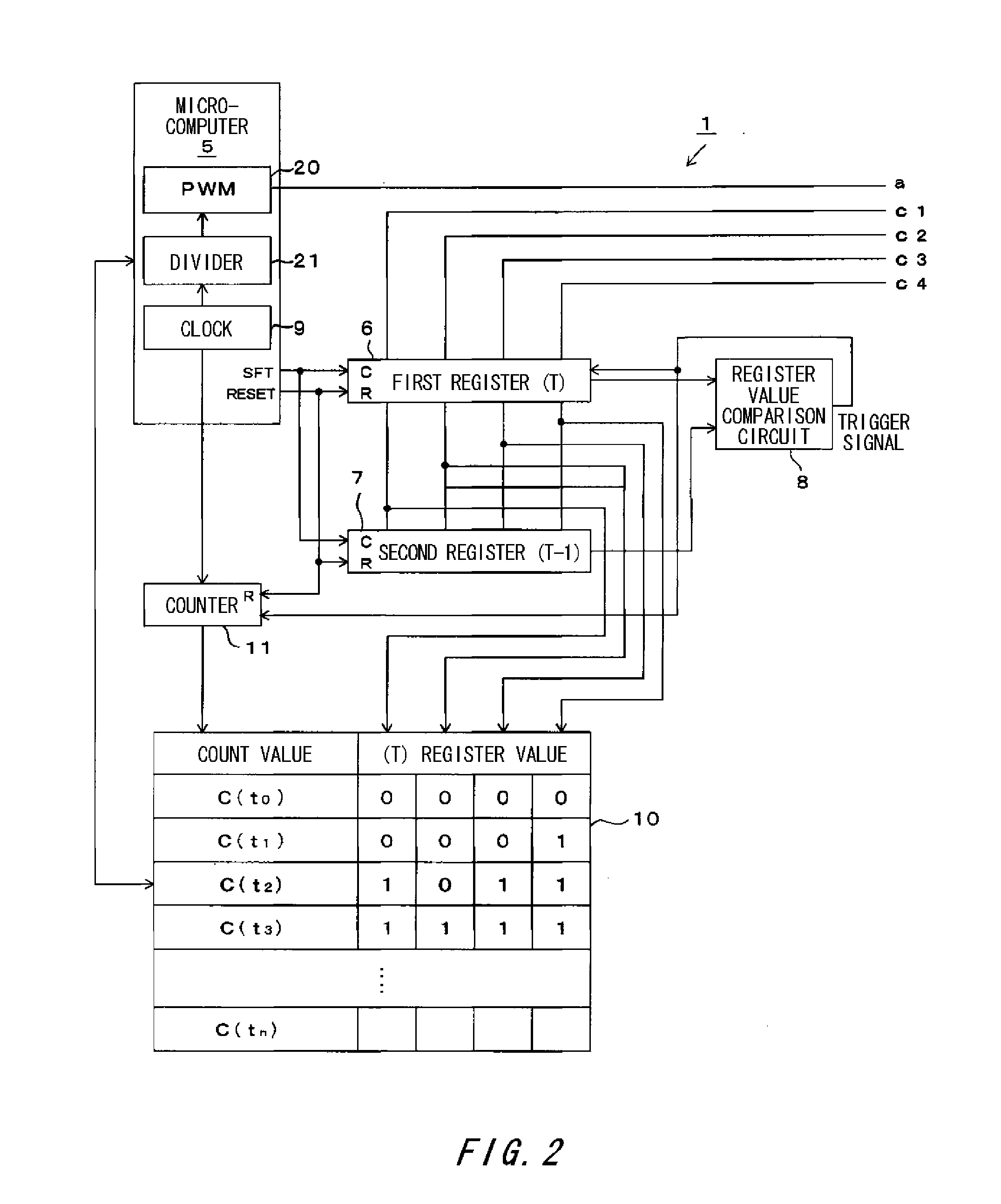
[0037]A capacitive touch panel (hereinafter called a touch panel) 1 according to an embodiment of the invention will be described below by using FIGS. 1 to 4. The touch panel 1 includes a plurality of sensing electrodes 31, 32, 33 and 34 formed on an insulating panel not shown with an insulation distance of some millimeters therebetween, for example. The stray capacitance Cs of each of the sensing electrodes 3 is expressed as a total of the capacitance of a surrounding conductive pattern, capacitance of a shield case to shield a unit, and capacitance formed between the sensing electrode and the ground. The stray capacitance Cs increases in response to approach of an input unit such as a finger while other capacitances are kept at substantially constant levels. The stray capacitances Cs1, Cs2, Cs3 and Cs4 of the respective sensing electrodes 3 are compared, and a sensing electrode 3 having the highest stray capacitance Cs compared with the others is regarded as that an input unit hav...


PUM


Abstract

Changes of the stray capacitances of a large number of sensing electrodes can be detected simultaneously. Further, even if a stray capacitance changes slightly, an input operation to a sensing electrode can be detected based on elapsed time until the electric potential of the sensing electrode becomes the same as a threshold potential. The stray capacitance of a sensing electrode and a resistor of the sensing electrode form a CR time constant circuit. Charge or discharge of the stray capacitance of the sensing electrode is controlled while a rest time in a predetermined time ratio is set. A stray capacitance that slightly increases in response to an input operation made near a sensing electrode can be detected by detecting the stray capacitance in extended elapsed time until the electric potential of the sensing electrode becomes the same as the threshold potential.

Description

CROSS REFERENCE TO RELATED APPLICATION[0001]The contents of the following Japanese patent application and International patent application are incorporated herein by reference:[0002]Japanese Patent Application NO. 2010-047642 filed on Mar. 4, 2010, and[0003]International Patent Application NO. PCT / JP2010 / 004707 filed on Jul. 23, 2010.BACKGROUND[0004]1. Technical Field[0005]The invention relates to a capacitive touch panel for detecting an input operation in a noncontact manner made to a sensing electrode arranged on an insulating panel based on increase of the stray capacitance of the sensing electrode.[0006]2. Related Art[0007]A capacitive touch panel is known as a pointing device for designating an item such as an icon displayed on a display of an electronic device. An electrostatic capacitance changes near a position on an entry screen as an input unit such as a finger is approaching. By making use of this phenomenon, the capacitive touch panel can detect an input operation in a ...

Claims


Application Information

Patent Timeline
IPC IPC(8): G01R27/26
CPCG06F3/0416H03K17/9622G06F3/044G06F3/04166G06F3/04182
Inventor YOSHIKAWA, OSAMU
Owner SMK CORP
Why Eureka
Try Eureka