User device dormancy

Active Publication Date: 2012-01-26
QUALCOMM INC
View PDF21 Cites 57 Cited by
  • Summary
  • Abstract
  • Description
  • Claims
  • Application Information

AI Technical Summary

Benefits of technology

[0011]One particular advantage provided by at least one of the disclosed embodiments is reduced power consumption at a communication device by selectively re-sending a message to cause a network to transition the communication device to a low-power state after a data session has ended. For ex

Problems solved by technology

For example, a first message from the commu

Method used


Image

  • User device dormancy
  • User device dormancy
  • User device dormancy

Examples


first embodiment

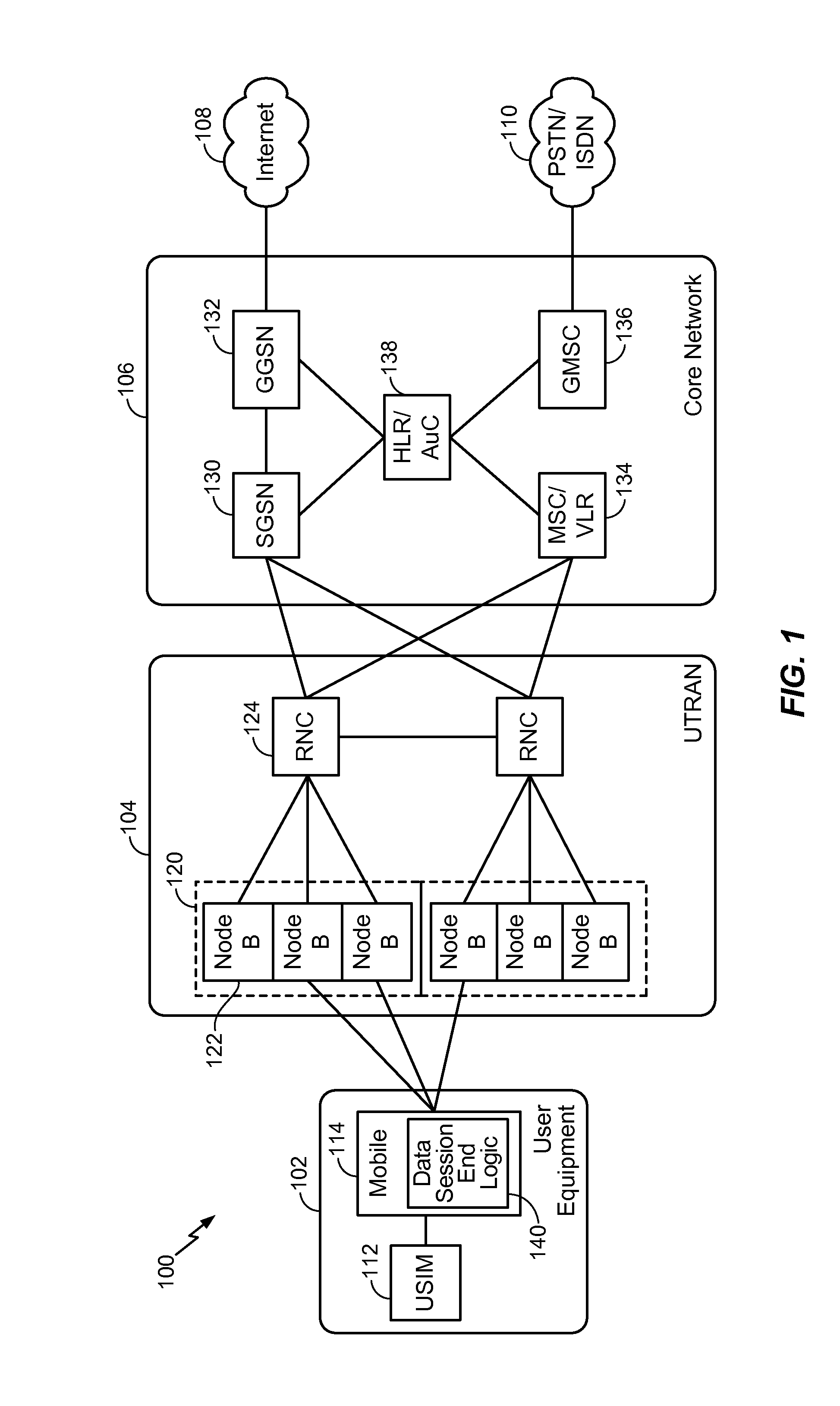
[0020]Referring to FIG. 1, a communication system is depicted and designated 100. The system 100 includes user equipment 102 in communication with an access network 104, such as a universal mobile telecommunications system (UMTS) terrestrial radio access network (UTRAN). The access network 104 is coupled to a core network 106. The core network 106 is coupled to a packet-switched network, such as the internet 108, and is coupled to one or more other networks, such as a public switched telephone network (PSTN) and / or an integrated services digital network (ISDN) 110.

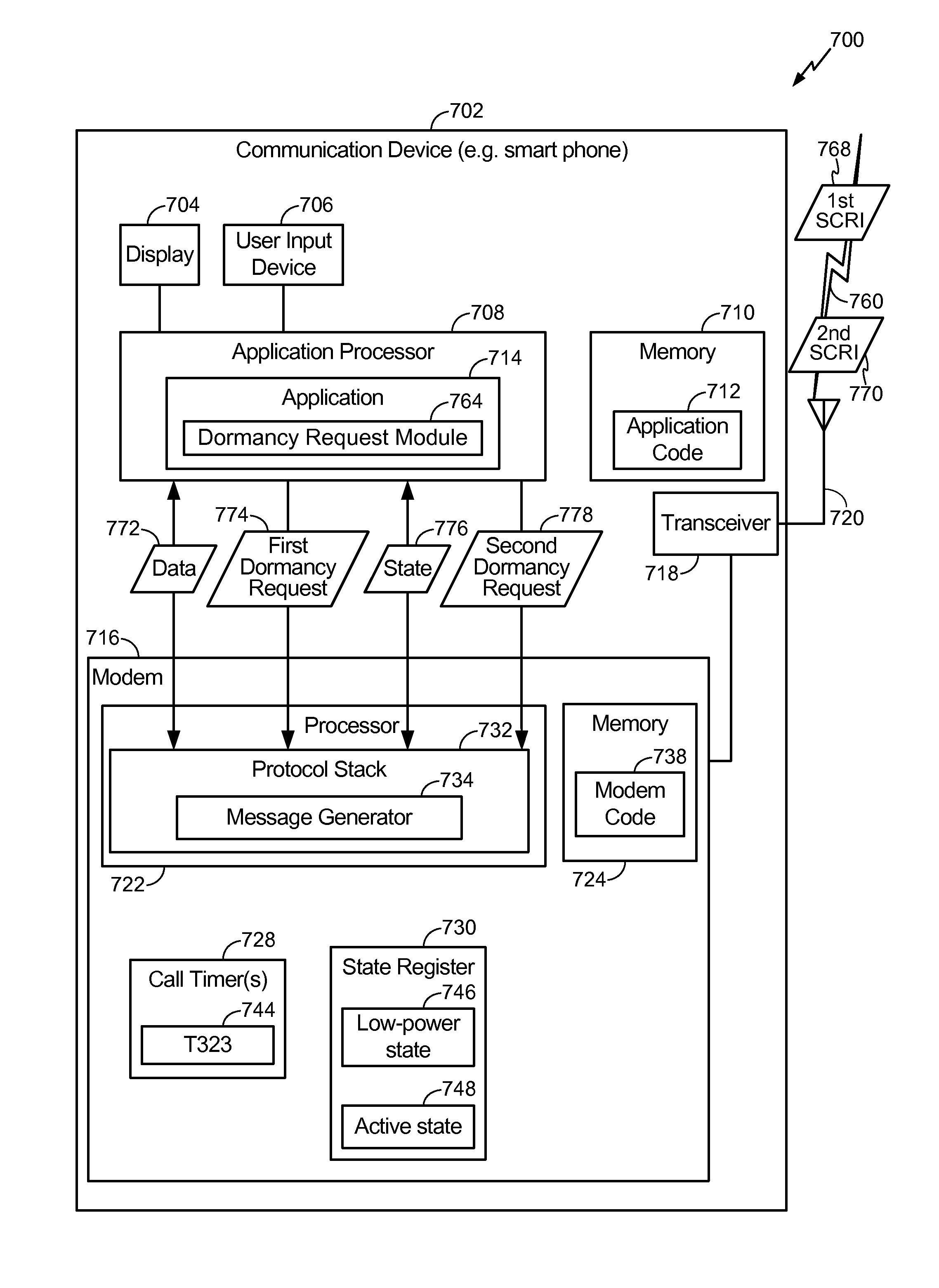
[0021]The user equipment 102 includes a module 112 that may identify a user's subscription information, such as a universal subscriber identity module (USIM) coupled to a communication device 114. The communication device 114 may be a mobile phone such as a smart phone. As other examples, the communication device 114 may be a fixed station, a data terminal, or another type of communication device. The communication device ...

third embodiment

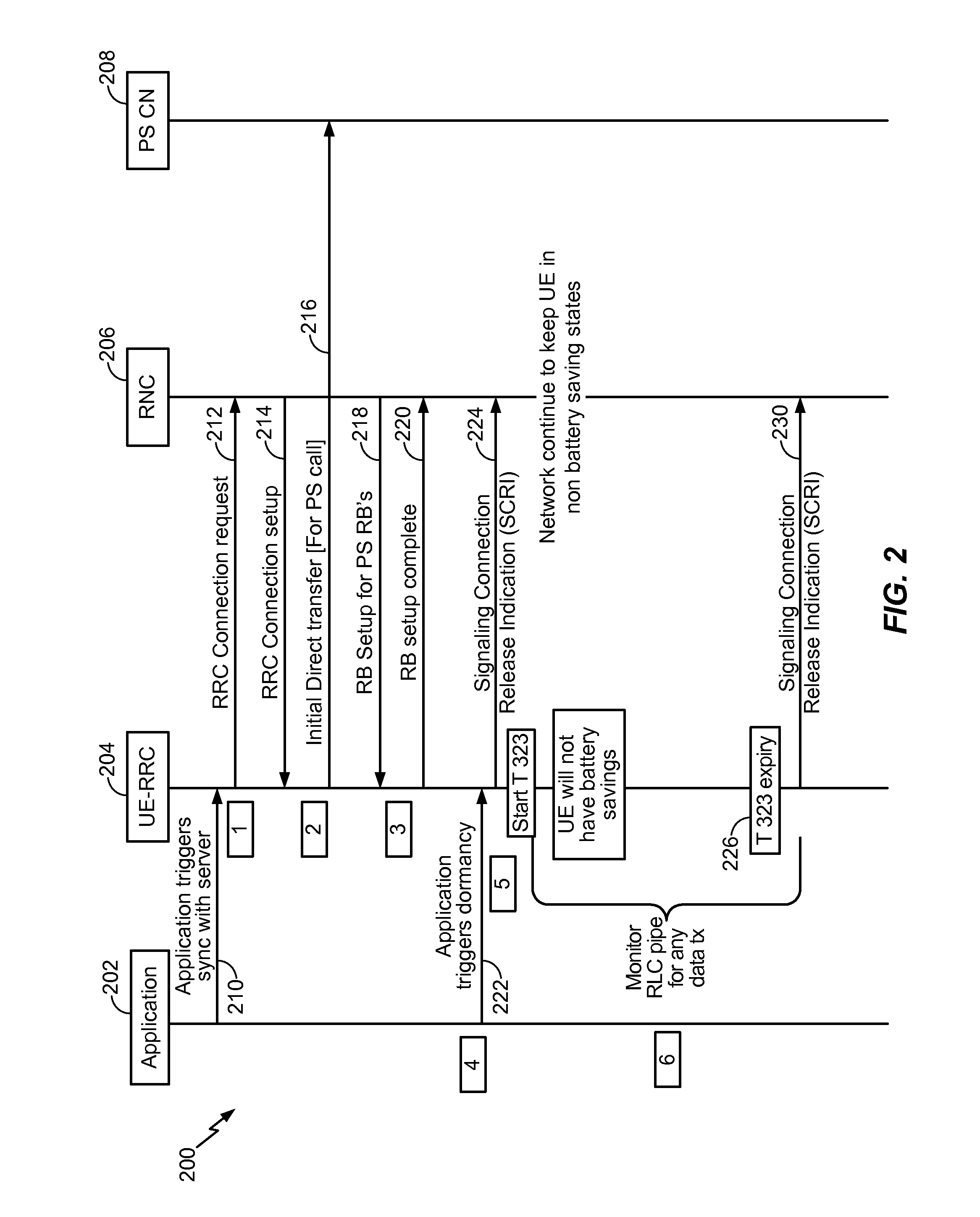
[0057]FIG. 4 illustrates a method of determining whether to re-send a message indicating that a data session has ended. The example of FIG. 4 illustrates operation in an embodiment using fast dormancy of a UMTS network that is not responsive to an SCRI from a mobile device. Signaling is illustrated between a user application 402 and a radio resource control (RRC) of user equipment (UE) (UE-RRC) 404 with a radio network controller (RNC) 406 and a packet switched domain (PS CN) 408. For example, FIG. 4 may correspond to communication of the UE 102 to the internet 108 via the access network 104 of FIG. 1.

[0058]1. The user application 402 (for example, an email client that synchronizes 410 with a server once every ten minutes) makes a packet switched (PS) data call that causes the UE-RRC 404 to send a RRC connection request message 412 to establish a RRC connection 414.

[0059]2. The PS domain is opened by the UE sending an initial direct transfer (IDT) message 416.

[0060]3. The network se...

fourth embodiment

[0066]FIG. 5 illustrates a method of selectively resending a dormancy request. The method 500 includes determining whether a dormancy request is received from an application executing at a communication device, at 502. For example, the application may be the user application 402 of FIG. 4. When it is determined that a dormancy request is received from an application executing at the communication device, a message is sent indicating that a data session has ended, at 504. The message may be sent from the communication device to a radio network controller, such as the SCRI message 424 sent to the RNC 406 of FIG. 4. The communication device may be configurable to transition between an active state and a low-power state, and the communication device may be in the active state when the message is sent.

[0067]A determination is made whether a time period following the sending of the message has expired, at 506. For example, the time period may be the time period described with respect to F...


PUM


Abstract

In a particular embodiment, a method includes sending a message from a communication device to a radio network controller. The message indicates that a data session has ended. The data session is supported by a wireless channel between the communication device and the radio network controller. After a time period following the sending of the message, a second message is selectively sent to the radio network controller. The second message indicates that the data session has ended. The second message is selectively sent based at least in part on whether a measurement indicates that data was communicated via the wireless channel during the time period.

Description

I. CLAIM OF PRIORITY[0001]The present application claims priority from U.S. Provisional Patent Application No. 61 / 367,160 filed on Jul. 23, 2010, the contents of which are expressly incorporated herein by reference in their entirety.II. FIELD[0002]The present disclosure is generally related to wireless communication systems.III. DESCRIPTION OF RELATED ART[0003]Advances in technology have resulted in smaller and more powerful computing devices. For example, there currently exist a variety of portable personal computing devices, including wireless computing devices, such as portable wireless telephones, personal digital assistants (PDAs), and paging devices that are small, lightweight, and easily carried by users. More specifically, portable wireless telephones, such as cellular telephones and Internet Protocol (IP) telephones, can communicate voice and data packets over wireless networks. Many such wireless telephones incorporate additional devices to provide enhanced functionality f...

Claims


Application Information

Patent Timeline
IPC IPC(8): H04W24/00H04L5/16H04L12/26
CPCH04W76/068H04L67/143H04W76/046H04W52/0235H04W52/0209H04W76/38H04W76/27Y02D30/70H04W24/00H04W76/30H04W52/02
Inventor PATIL, KIRAN KISHANRAOSANKA, SURESHKRISHNAMOORTHY, SATHISH
Owner QUALCOMM INC
Why Eureka
Try Eureka