Method of coincidence detection and tomography system using the same

Inactive Publication Date: 2012-02-02
INST NUCLEAR ENERGY RES ROCAEC
View PDF3 Cites 3 Cited by
  • Summary
  • Abstract
  • Description
  • Claims
  • Application Information

AI Technical Summary

Benefits of technology

[0009]The present invention is directed to a method of coincidence detection and a tomography system using the same, which are capable of completing tasks, such as preliminary screening of event matching, matching information coding, and determination of whether a single or multiple coincidences occur, at the instant of a rising edge of a system main clock. Therefore, as compared with the conventional hybrid method in which the trigger signal AND logic method is used to perform preliminary screening of the coincidence first and coding and multiple event judgment are performed later, the present invention has advantages such as good real-time performance, rapidness, and high integrity in terms of real-time computation, and the event relation table is easy to be implemented by a memory module in hardware.
[0010]The present invention is directed to a method of coincidence detection and a tomography system using the same, in which only time marks of modules that may possibly have a coincidence after preliminary screening are compared, thus avoiding the process of complicatedly comparing all time mark signals in the conventional pure time mark method. After the preliminary screening, the judgment of a coincidence is finally performed through the time mark method, so as to avoid the distortion due to the affect of noise or interference when merely the trigger signals are used to perform judgment, thus reducing the probability of event misjudgment. Therefore, the present invention has high detection precision of the convention hybrid method and time mark method, and is capable of reducing the complexity of the coincidence detection system circuit, and improving the real-time performance and integrity of the system.

Problems solved by technology

This method can provide a precise time resolution; however, the complexity thereof increases along with the increase of a digital value length of the time mark, thus causing poor real-time performance of the detection system circuit.
However, a size of the coincidence time window is determined by a pulse width of the trigger signal, which is not suitable for being altered or adjusted in real time, and the trigger signal is easy to be affected by noises of the circuit and elements.

Method used


Image

  • Method of coincidence detection and tomography system using the same
  • Method of coincidence detection and tomography system using the same
  • Method of coincidence detection and tomography system using the same

Examples


Embodiment Construction

[0021]In order to make the features, objectives, and functions of the present invention more comprehensible, a detailed structure of a device of the present invention and a design idea thereof are further described in detail below, for the Examiner to understand the characteristics of the present invention.

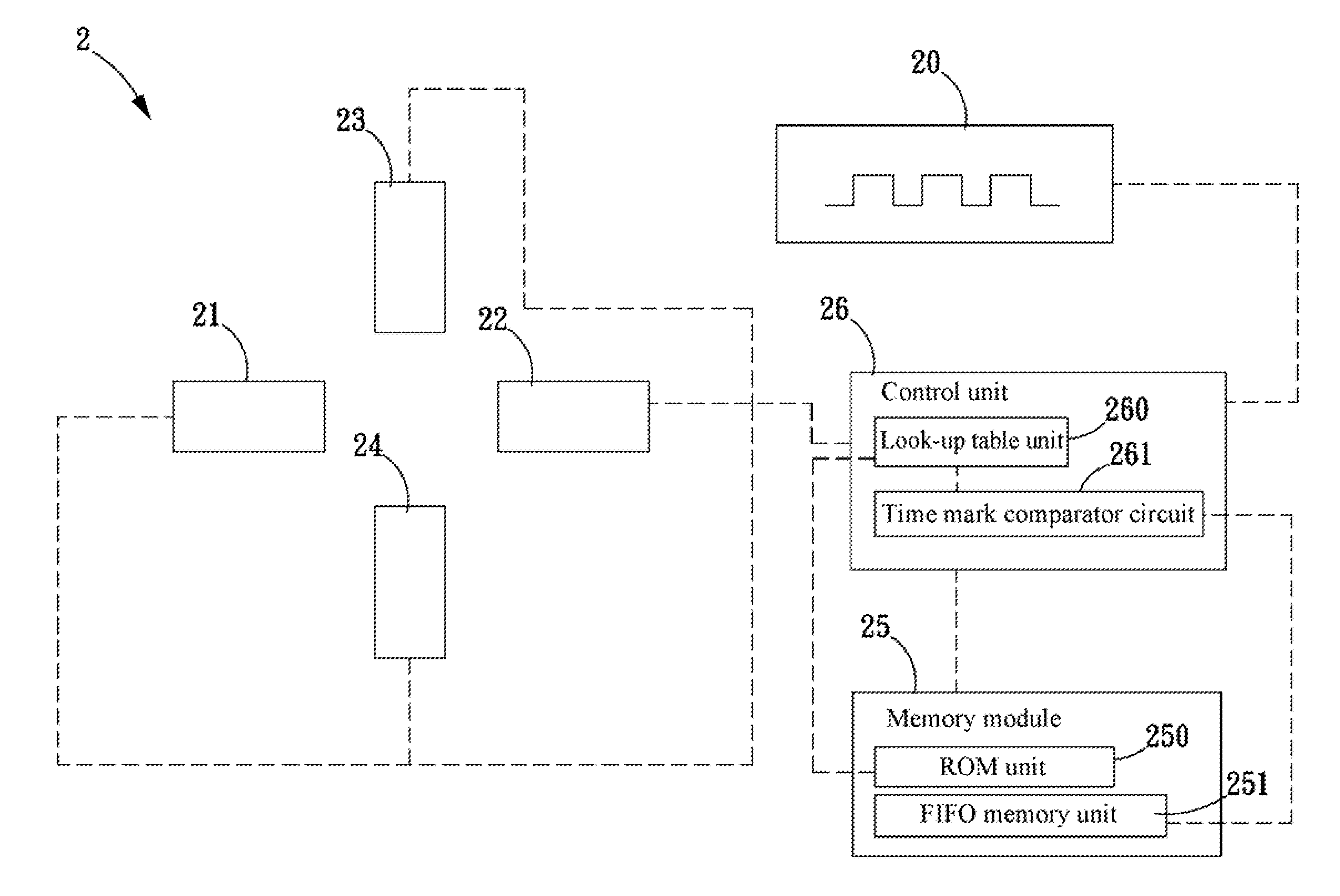
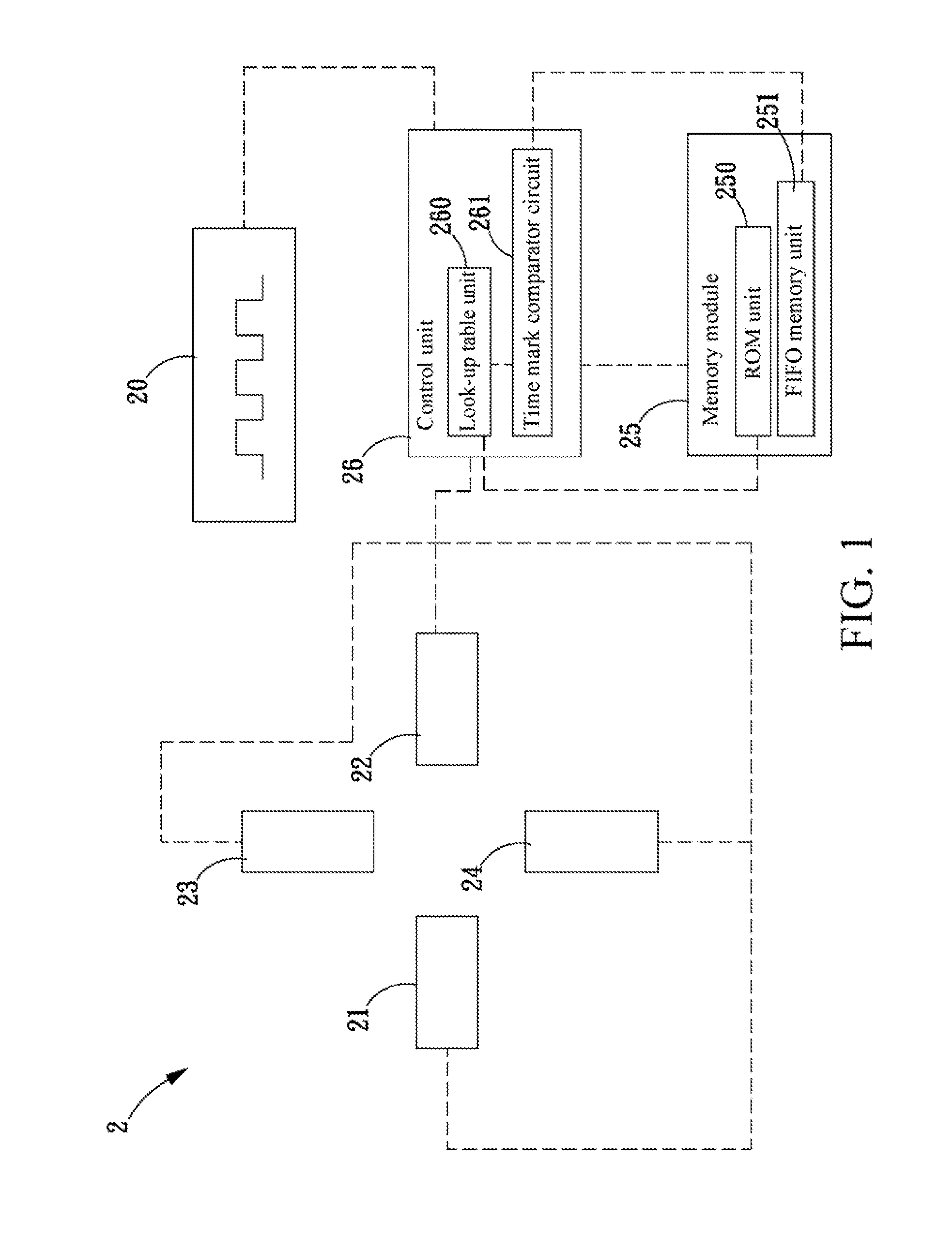
[0022]Referring to FIG. 1, a schematic view of a tomography system according to an embodiment of the present invention is shown. The tomography system 2 includes: a main clock generator 20, a plurality of radiation detectors 21-24, a memory module 25, and a control unit 26. The main clock generator 20 is used for generating a main clock signal. The plurality of radiation detectors 21-24 is used for respectively detecting a radiation event (for example, γ-ray) to generate a corresponding trigger signal. The mode of generating the trigger signal belongs to the conventional art, and is not repeated herein. In this embodiment, every two of the plurality of radiation detectors 21-24 ar...


PUM


Abstract

A method of coincidence detection and a tomography system using the same are provided. In the method and system, by combining original trigger signals and time mark information, at a time point of a rising edge of a system main clock, a combination of the trigger signals of a plurality of radiation detectors of the system is obtained, and a type of the combination of the trigger signals is determined according to a predetermined event relation. If the combination of the trigger signals belongs to an effective event, a time mark procedure is utilised for judging the trigger signals in the event, in which it is determined whether a difference between two time mark information respectively associated with the trigger signals of the two corresponding radiation detectors is within a coincidence time window or not, thereby judging whether the effective event is an annihilation event.

Description

BACKGROUND OF THE INVENTION[0001]1. Field of Invention[0002]The present invention relates to a coincidence detection technology, and more particularly, to a method of coincidence detection and a tomography system using the same in which event recognition is performed by combining detection of trigger signals using a signal rising edge of a main clock and a time difference associated to the trigger signals.[0003]2. Related Art[0004]Positron Emission Tomography (PET) performs medical examination to creatures by using isotope medicine with little radioactivity. After intravenously injecting glucose with radioactive medicine in the body of a creature, the medicine is absorbed by malignant cells in a large amount, positrons during the decay process impact with electrons in the cells to counteract with each other thus generating annihilation, the mass disappears and two γ-rays in opposite directions and having an included angle of 180 degrees are emitted, in which each γ-ray has an energy...

Claims


Application Information

Patent Timeline
IPC IPC(8): G01T1/172
CPCG01T1/1647
Inventor WU, TZONG-DARCHANG, CHUNG-HUNGJAN, MEEI-LING
Owner INST NUCLEAR ENERGY RES ROCAEC
Why Eureka
Try Eureka