Photovoltaic inverter system and method of starting same at high open-circuit voltage

a photovoltaic inverter and open-circuit voltage technology, applied in the field of solar power generation, can solve the problems of reducing efficiency, higher conduction loss, and higher cost of higher rated power electronic devices

Active Publication Date: 2012-02-02
GENERAL ELECTRIC CO
View PDF5 Cites 132 Cited by
  • Summary
  • Abstract
  • Description
  • Claims
  • Application Information

AI Technical Summary

Benefits of technology

[0019]activating a DC link voltage control and regulating the DC link voltage to about the minimum level that allows control of grid currents generated via the inverter; and
[0020]connecting the DC voltage source to the power inverter system subsequent to activating the DC link voltage control and regulating the DC link voltage to abou

Problems solved by technology

Higher rated power electronic devices are typically more expensive and have higher conduction losses, leading to reduced efficiency.
Moreover, the use of power electronic devices rated for a voltage higher than the maximum power voltage results in reduced operating efficiency.
However, during startup or during other transient conditions when the PV array is first coupled, decoupled, or re-coupl

Method used


Image

  • Photovoltaic inverter system and method of starting same at high open-circuit voltage
  • Photovoltaic inverter system and method of starting same at high open-circuit voltage
  • Photovoltaic inverter system and method of starting same at high open-circuit voltage

Examples


Embodiment Construction

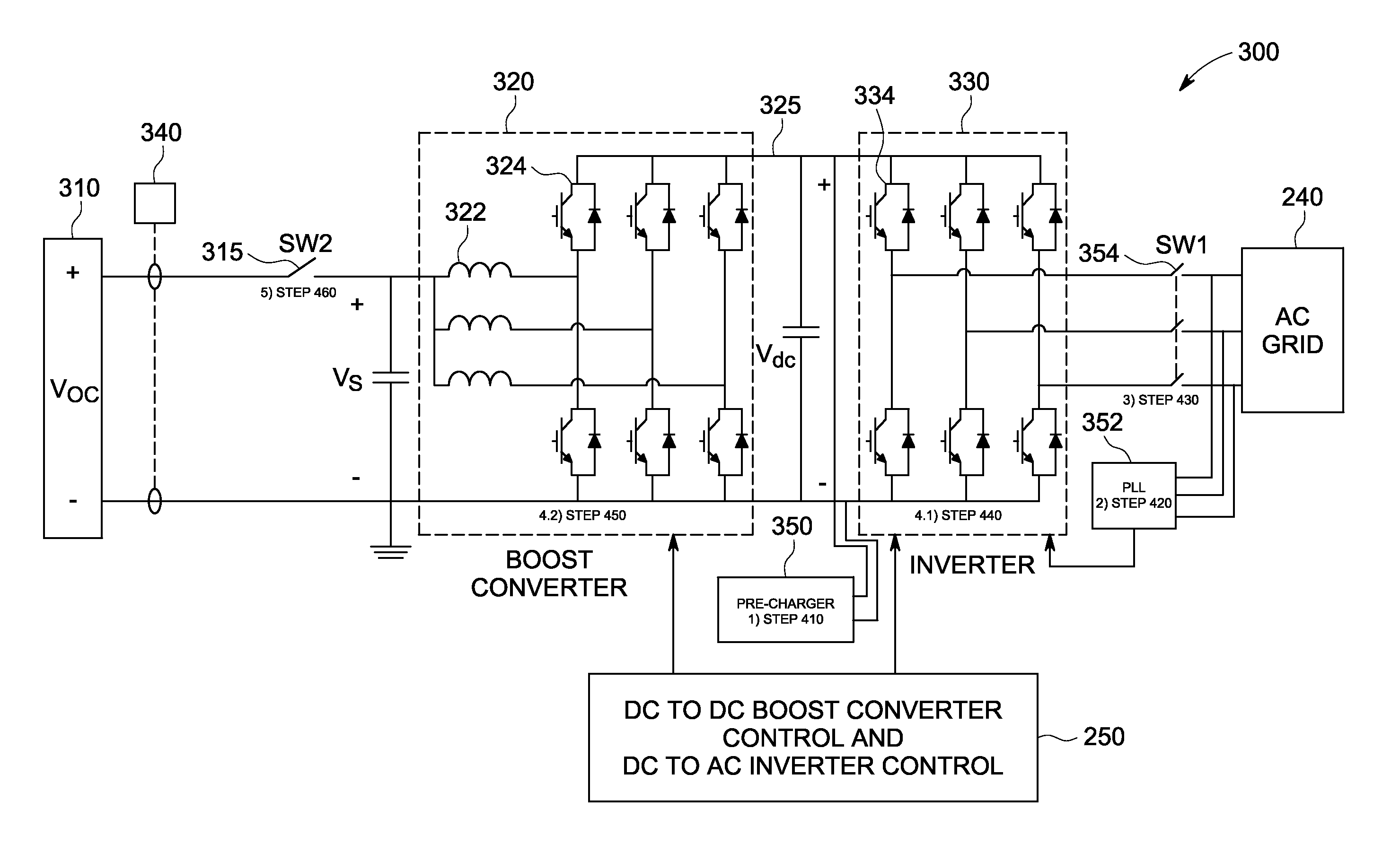
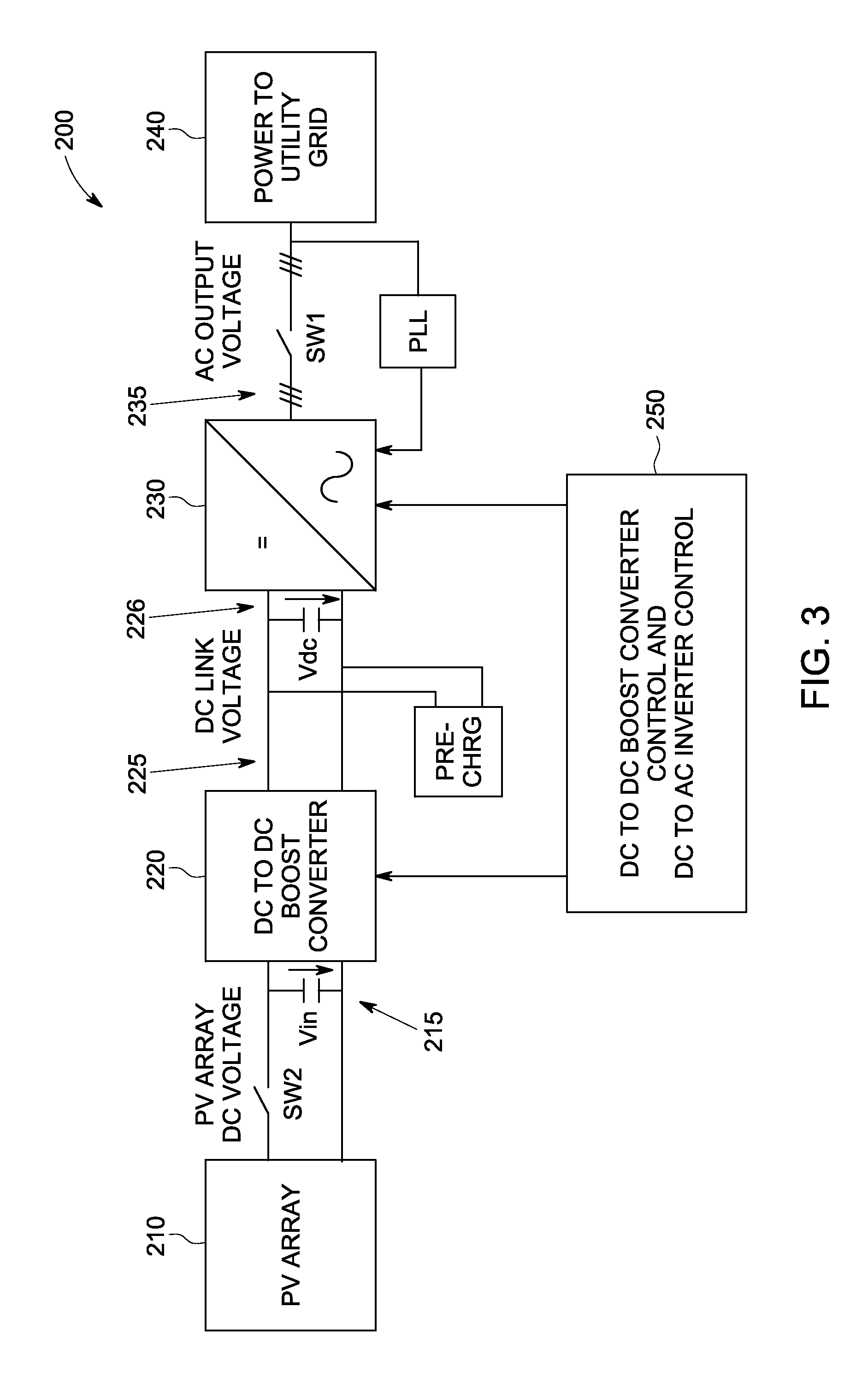
[0039]FIG. 3 depicts a block diagram of a two stage PV power converter system 200 used to convert DC power 215 generated by a PV array 210 into AC power 235 suitable for feeding an AC power grid 240. The first stage of power converter system 200 can include a DC to DC converter 220, such as a boost converter, that provides DC power 225 to a DC link 226. The DC link 226 couples the DC to DC converter 220 to an inverter 230 which operates as the second stage of the power converter 200. Inverter 230 converts the DC power 225 on the DC link 226 to AC power 235 suitable for being supplied to an AC power grid 240. DC to DC converter 220 can be a part of or integral with inverter 230 or can be a separate stand alone structure from inverter 230. In addition, more than one converter 220 can be coupled to the same inverter 230 through one or more DC links.

[0040]Power converter system 200 includes a control system 250 that is configured to control both the DC to DC boost converter 220 and the ...


PUM


Abstract

A power inverter system includes a DC to AC inverter configured to convert DC voltage from a DC power source to AC voltage. A DC link couples the DC power source and the inverter. An inverter pre-charger operates to pre-charge the inverter to achieve a desired DC link voltage prior to connecting the power inverter system to an AC power grid. A phased lock loop synchronizes the pre-charged inverter to the AC power grid prior to connecting the power inverter system to the AC power grid. The pre-charged inverter regulates the DC link voltage to about the minimum voltage level that allows control of AC grid currents via the inverter subsequent to connecting the power inverter system to the AC grid. The inverter operates in a maximum power point tracking control mode only subsequent to a first voltage transient caused by connecting the DC power source to energize the power inverter system.

Description

BACKGROUND[0001]This invention relates generally to the field of solar power generation and, more particularly, to methods and systems to allow for a high DC source voltage in a solar power converter system.[0002]Solar power generation is becoming a progressively larger source of energy throughout the world. Solar power generation systems typically include one or more photovoltaic arrays (PV arrays) having multiple interconnected solar cells that convert solar energy into DC power through the photovoltaic effect. In order to interface the output of the PV arrays to a utility grid, a power converter system is used to change the DC current and DC voltage output of the PV array into a 60 / 50 Hz AC current waveform that feeds power to the utility grid.[0003]Various power converter systems exist for interfacing the DC output of a PV array (or other DC power source) with the AC grid. One implementation of a power converter system includes two stages, a boost converter stage and an inverter...

Claims


Application Information

Patent Timeline
IPC IPC(8): H02M7/48
CPCH02M3/1584H02M7/48H02J2300/22H02J2300/24H02J3/381Y02E10/56H02J2300/26H02J3/46
Inventor SCHROEDER, STEFANSHEN, JIEEL-BARBARI, SAID FAROUK SAIDROESNER, ROBERT
Owner GENERAL ELECTRIC CO
Why Eureka
Try Eureka