Communication system, apparatus and methods for calibrating an antenna array

a technology of communication system and antenna array, applied in the direction of polarisation/directional diversity, transmission monitoring, receiver monitoring, etc., can solve the problem of not experiencing the same processing gain as a coherent desired signal, inability to individually receive beams for a specific user, and poor power efficiency, etc. problem, to achieve the effect of reducing one or more problems, and reducing the number of problems

Active Publication Date: 2012-02-02
ANALOG DEVICES INT UNLTD
View PDF9 Cites 54 Cited by
  • Summary
  • Abstract
  • Description
  • Claims
  • Application Information

AI Technical Summary

Benefits of technology

[0015]Accordingly, the invention seeks to mitigate, alleviate or eliminate o

Problems solved by technology

Major efforts have been underway in recent years to improve this poor power efficiency by utilising schemes such as adaptive predistortion.
In addition, thermal noise from multiple sources also exhibits incoherent properties, and thus when added the signals from multiple sources do not experience the same processing gain as a coherent desired signal.
Individual receive beam-forming for a specific user is not feasible, since there is likely to be multiple received signals of comparable powers from different UEs simultaneously at the antenna array.
Thus, maintaining clock phase synchronization to such devices across the array of elements is becoming increasingly difficult.
Furthermore, samples processed in the digital domain ma

Method used


Image

  • Communication system, apparatus and methods for calibrating an antenna array
  • Communication system, apparatus and methods for calibrating an antenna array
  • Communication system, apparatus and methods for calibrating an antenna array

Examples


Embodiment Construction

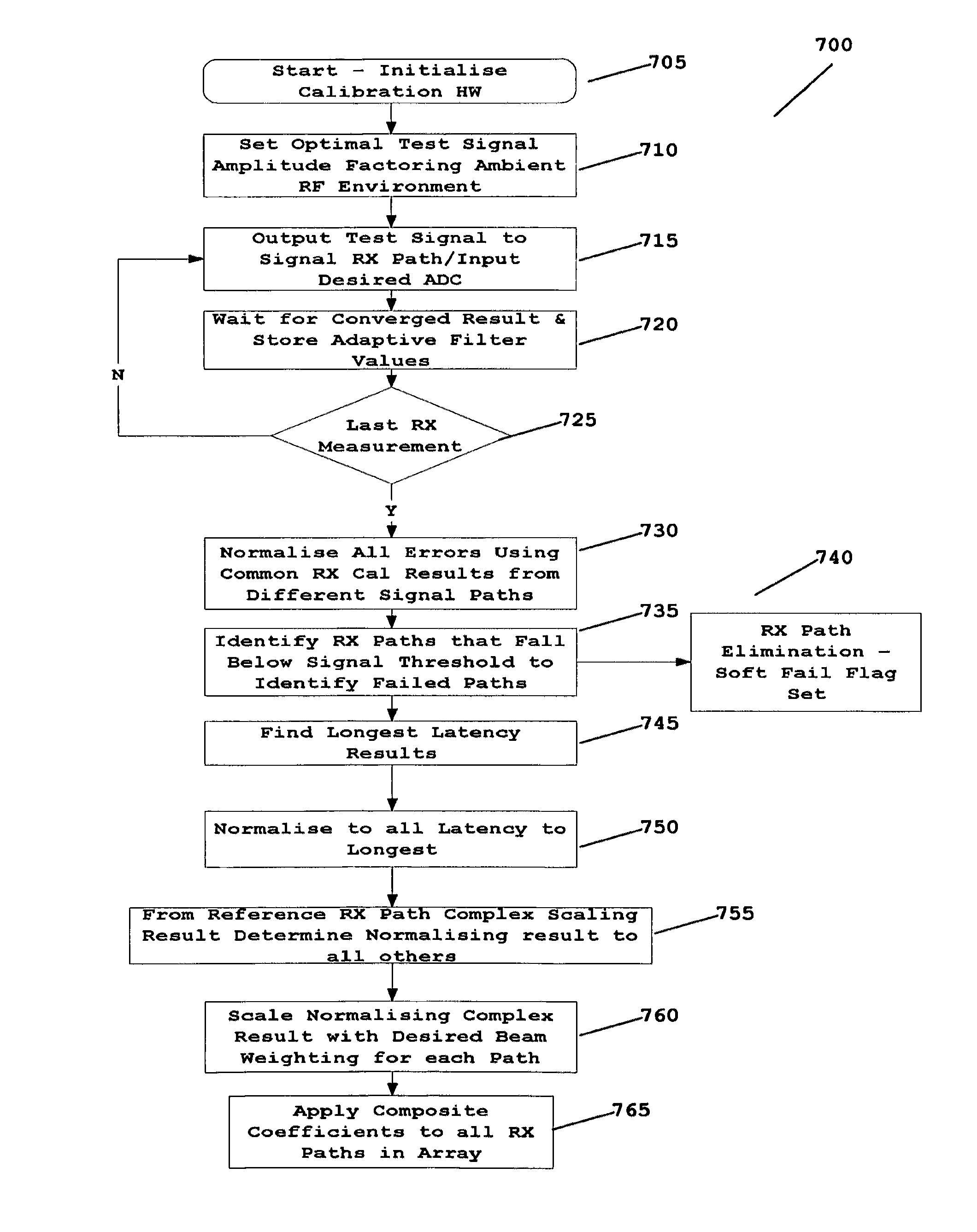
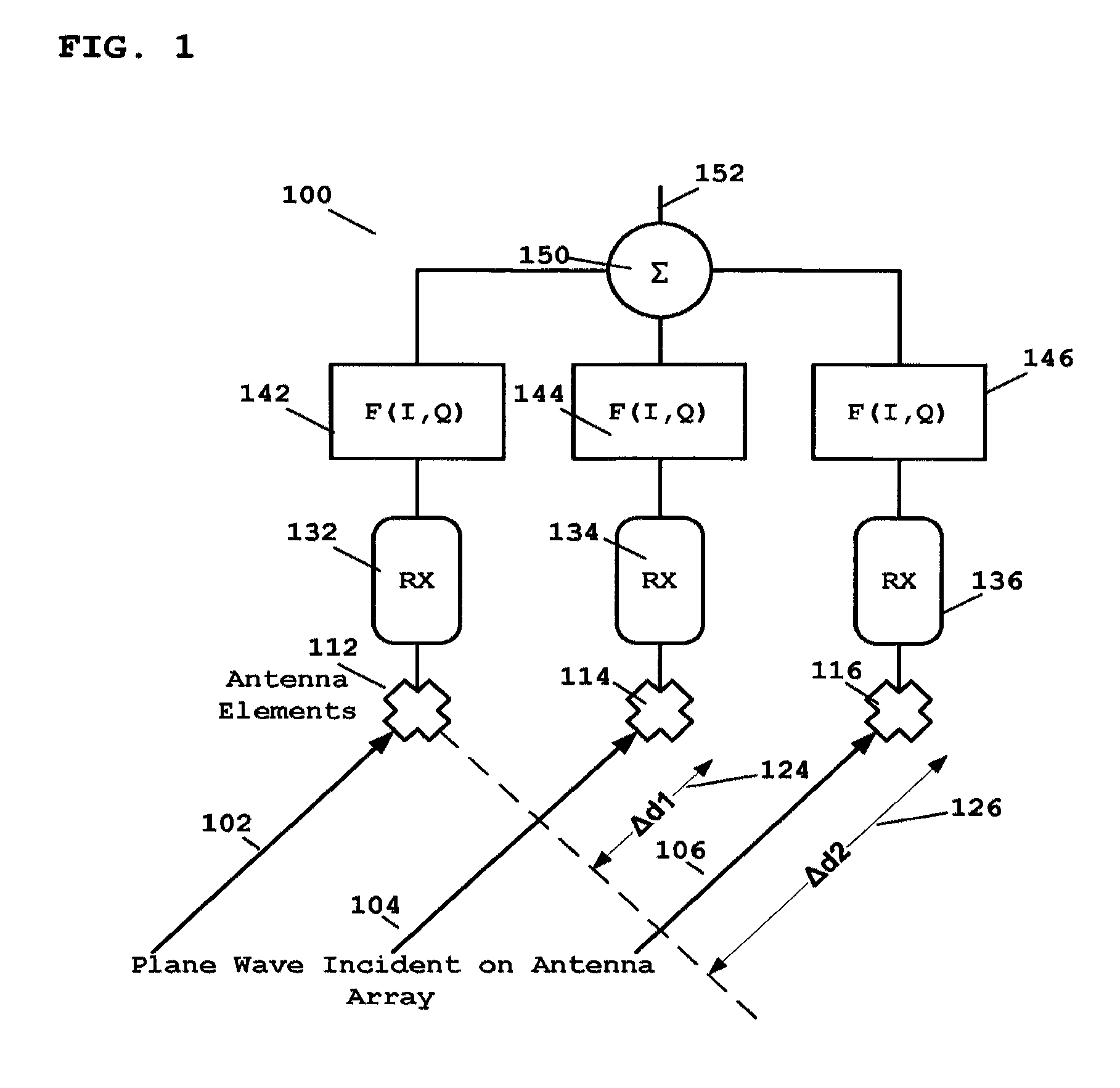
[0050]In the field of radio-array active antenna technology, receive signals are additively combined coherently from the different receiver (Rx) elements. This receive combining operation may be implemented in the digital domain. For optimal coherency to exist on the separate signals at the combining stage, the latency, phase response and gain response of the respective receive paths should be equalised. Different receivers in an array may exhibit variations in these characteristics due to, say, component manufacturing tolerances, clock skew, temperature and power supply variations, etc. For example, in practical systems, there will be different instantiations of voltage regulators, and therefore different devices may exhibit process-induced offsets and temperature-dependent coefficients. Similarly, the clock distribution to multiple transceivers undergoes variations in the clock path, thereby causing an offset in relative phase to each transceiver. It is also known that temperature...


PUM


Abstract

A method for calibrating (700) an antenna array comprises a plurality of antenna elements coupled to a plurality of respective receive paths in a wireless communication system. The method comprises, in receive mode, applying a test signal to an individual single receive path (715) of the plurality of receive paths; and feeding back the test signal via a switched coupler network. The method further comprises running a receive calibration measurement routine to determine at least one measurement value used to calibrate the individual signal receive path and waiting for at least one converged measurement value; and extracting (720) the converged measurement value for at least one individual receive path. The steps of applying, running, extracting for a next individual single receive path are repeated until the calibration routine has completed (725). The method further comprises selecting a converged measurement value of at least one individual receive path from a plurality of receive paths (730) to form a reference receiver calibration result (730); normalizing a plurality of at least one measurement values of the plurality of receive paths using the reference receiver calibration result (730); and applying a normalized value to at least one of the plurality of receive paths.

Description

FIELD OF THE INVENTION[0001]The field of the invention relates to active antenna array arrangement for use in communication systems and in particular, but not exclusively, to calibration and control of active antenna arrays.BACKGROUND OF THE INVENTION[0002]Currently, 3rd generation (3G) cellular communication systems are being developed to further enhance the communication services provided to mobile phone users. The most widely adopted 3rd generation communication systems are based on Code Division Multiple Access (CDMA) technology. Carrier frequencies are used for both uplink transmissions, i.e. transmissions from a mobile wireless communication unit (often referred to as wireless subscriber communication unit or user equipment in 3rd generation systems) to the communication infrastructure via a wireless serving base station (often referred to as a Node-B in 3rd generation systems) and downlink transmissions, i.e. transmissions from the communication infrastructure to the mobile w...

Claims


Application Information

Patent Timeline
IPC IPC(8): H04B17/00
CPCH01Q1/246H01Q3/267H04B7/10H04B17/21H04B17/12H04B17/20H04B17/0085
Inventor O'KEEFFE, CONOR
Owner ANALOG DEVICES INT UNLTD
Why Eureka
Try Eureka