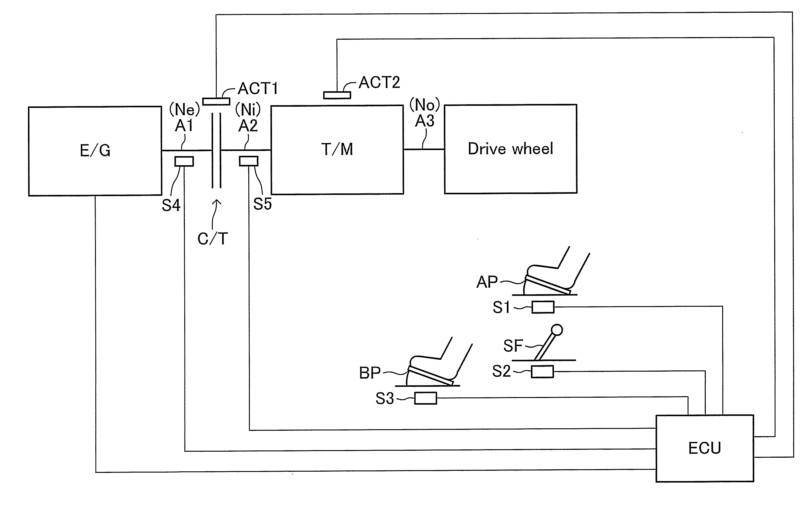
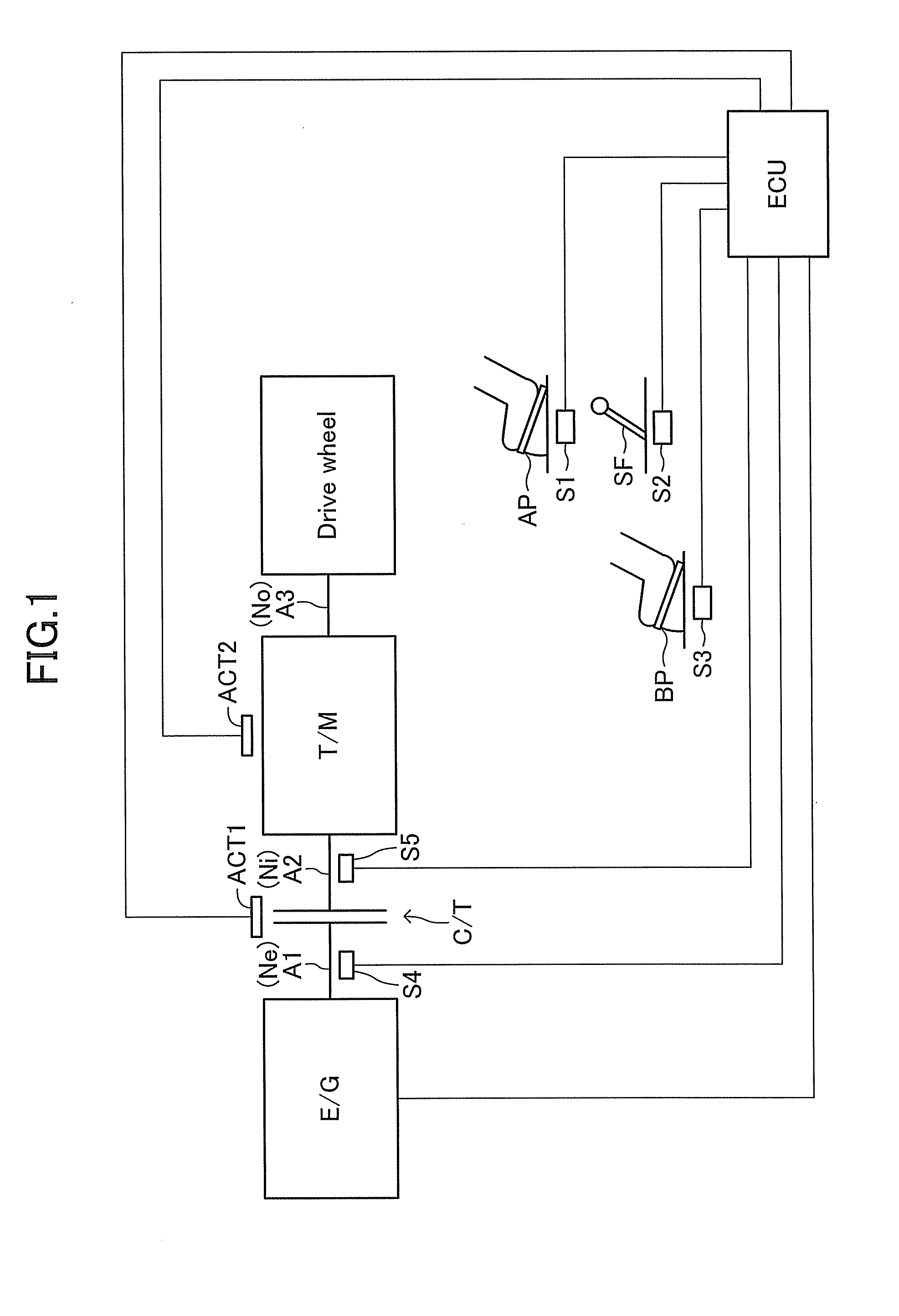
[0010]When the clutch is kept to be in the totally engagement state with the state in which the torsional vibration is generated on the drive
system as described above, the slip is not caused on the clutch, resulting in that an action (damping action) of suppressing the torsional vibration due to the slip on the clutch is not exerted. Therefore, the torsional vibration having relatively great amplitude is liable to be generated on the vehicle drive
system. It has been desired to suppress the generation of the torsional vibration having relatively great amplitude on the vehicle drive system.
[0011]The present invention aims to provide a vehicular power transmission control apparatus adapted to a vehicle having an AMT mounted thereto, the apparatus being capable of suppressing a torsional vibration on a vehicle drive system, which is liable to be generated when an operation amount of an acceleration operating member sharply decreases during the drive with a gear position at a lower speed range being selected.
[0019]When the acceleration pedal opening degree sharply decreases (particularly, to zero) from the great value in case where the vehicle drives with the state in which the gear position is fixed to the “specific gear position at the lower speed range”, the torsional vibration is liable to generate on the vehicle drive system afterward. When the clutch is kept to be in the totally engagement state in this case, the action (damping action) of suppressing the torsional vibration with the slip on the clutch is not exerted. On the other hand, when the clutch is kept to be in the semi-engagement state as in the configuration described above, the “damping action due to the slip on the clutch” described above is exerted to the torsional vibration. Accordingly, the torsional vibration on the vehicle drive system can be suppressed, whereby the torsional vibration having relatively great amplitude is difficult to occur.
[0020]In the power transmission control apparatus according to the present invention, it is preferable that, as the operation amount (acceleration pedal opening degree) of the acceleration operating member operated by a driver of the vehicle is greater, the predetermined value (A) is set to be smaller. When the vehicle drives with the state in which the clutch is kept to be in the semi-engagement state (when the clutch transmits the torque), heat is generated on the clutch due to the slip on the clutch. The amount of the generated heat increases, as the acceleration pedal opening degree increases, i.e., the torque transmitted by the clutch increases. Accordingly, when the acceleration pedal opening degree is great, some
countermeasure is to be preferably taken in order to suppress the excessively increased temperature of the clutch. On the other hand, the amount of the generated heat decreases, as the slip amount of the clutch (corresponding to the predetermined value) is smaller.
[0021]The configuration described above is based upon the knowledge described above. According to the configuration described above, the slip amount of the clutch is decreased, when the acceleration pedal opening degree is great. Accordingly, the amount of the generated heat is reduced, which prevents the clutch from having the excessive high temperature.
[0022]Similarly, it is preferable to configure the
control unit to set the predetermined value to be a smaller value, as the time when the state, in which the gear position of the transmission is set to the specific gear position at the lower speed range, is continued becomes longer. The case where the state, in which the vehicle drives with the clutch being kept to be in the semi-engagement state (the clutch transmits the torque), is continued for a long time means that the state in which the heat is generated on the clutch is continued for a long time. Accordingly, when the state in which the gear position is set to the “specific gear position at the lower speed range” is continued for a long time, some
countermeasure is to be preferably taken in order to suppress the excessively increased temperature of the clutch. The configuration described above is based upon the knowledge described above. According to the configuration described above, when the state in which the gear position is set to the “specific gear position at the lower speed range” is continued for a long time, the slip amount of the clutch is decreased. Consequently, the amount of the generated heat is reduced, which prevents the clutch from having the excessive high temperature.


