Ophthalmic lens with optical sectors

a technology of optical sectors and ophthalmology, applied in the field of ophthalmology, can solve the problems of ghost images and blur, further complicated, loss of contrast sensitivity, etc., and achieve the effects of maximizing light energy, and reducing blur and halo

Active Publication Date: 2012-02-02
TELEON HLDG BV
View PDF13 Cites 31 Cited by
  • Summary
  • Abstract
  • Description
  • Claims
  • Application Information

AI Technical Summary

Benefits of technology

[0014]In an embodiment, the lens comprises at least one recessed, semi-meridian optical sector which is radially and/or angularly subdivided into subzones. It thus may comprise an inner sector, an intermediate sector, and an outer sector, located within the (imaginary) boundary of the lens part. The inner sector has a first optical power, the intermediate sector which is adjacent to the inner sector has a second optical power. The outer sector adjacent to the intermediate sector has a third optical power. The step height between the boundaries of the semi-meridian sectors are joint by means of an optimised transition profile to maximize light energy directed to the macula and to reduce blur and halo's at bigger pupil sizes. The ophthalmic len

Problems solved by technology

This problem, also refers to as “pupil dependency”, is further complicated as the difference in pupil size varies substantially from patient to patient.
Another problem of those annular concentric designed MIOL are the ghost images and blur due to the light directed to the macula at the annular zone transitions.
Another big drawback of current MIOL is the loss of contrast sensitivity.
Due to the nature of diffractive optics, at least 20% of the incoming light will be lost and patients suffer from halos and glare.
It will be clear to a person skilled in the art that such a lens will suffer a large decrease of optical quality.
It has been found after extensive clinical testing that for a MIOL as disclosed in U.S. Pat. No. 6,409,339(B1), the transition profile used t

Method used


Image

  • Ophthalmic lens with optical sectors
  • Ophthalmic lens with optical sectors
  • Ophthalmic lens with optical sectors

Examples


examples

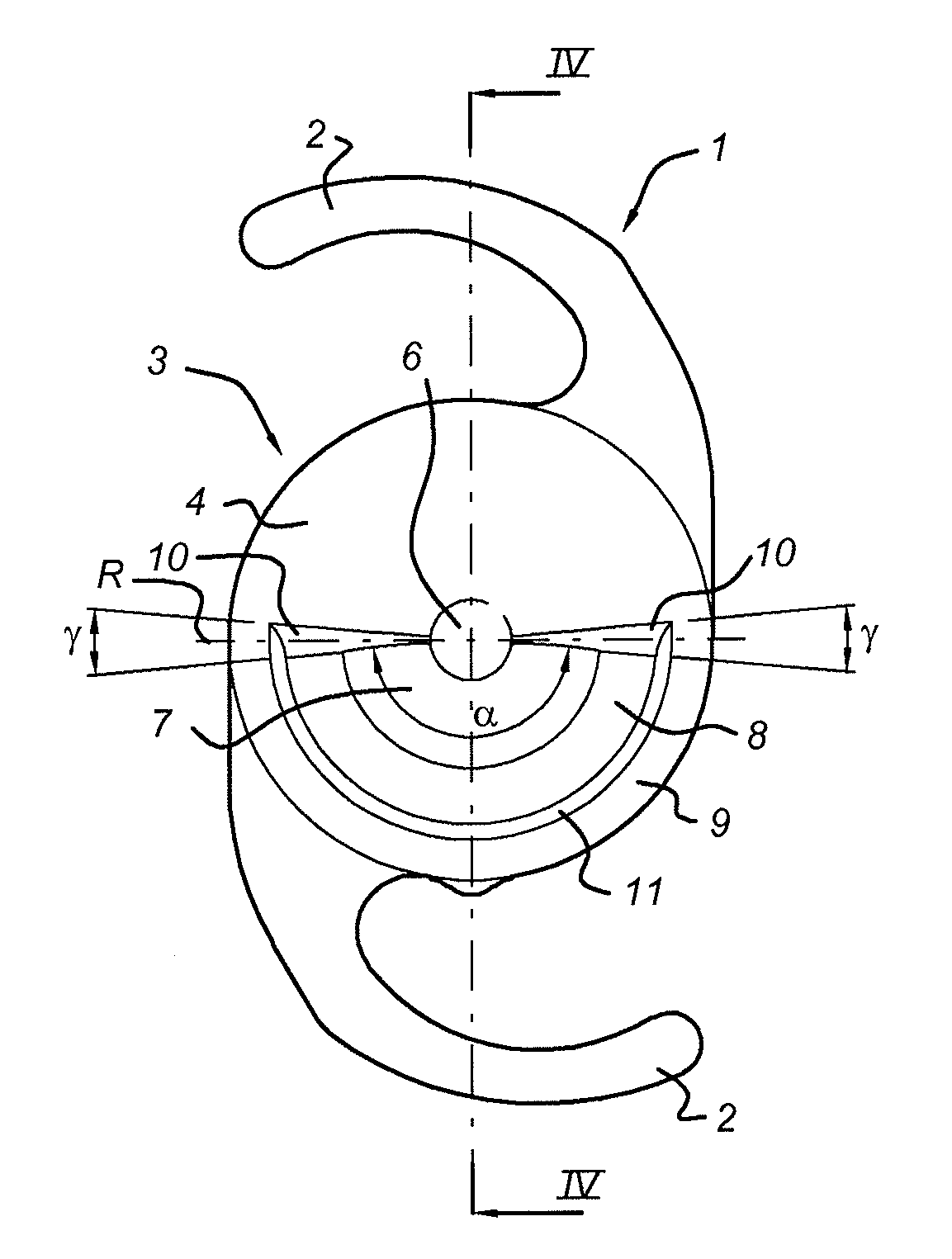
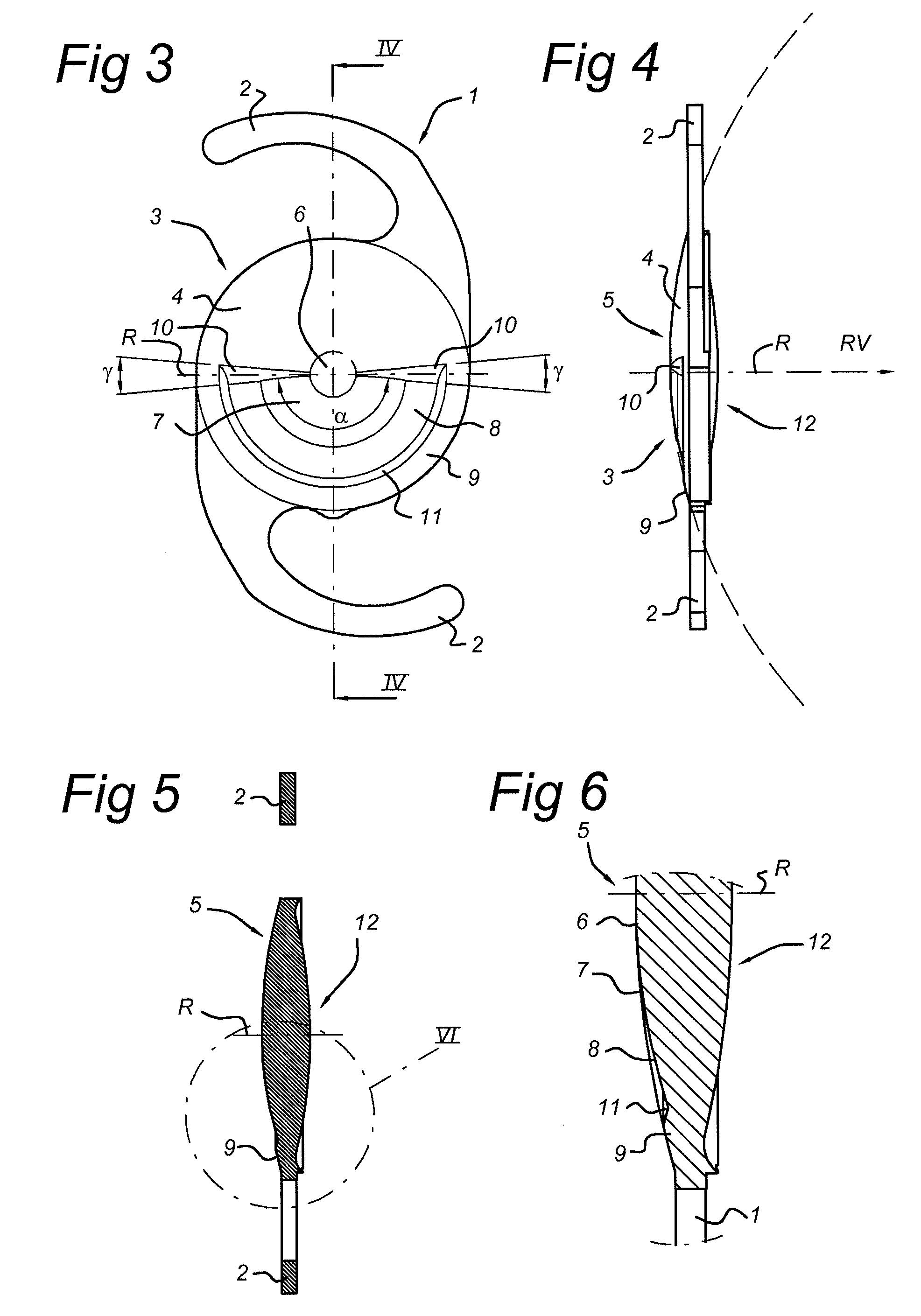
[0127]Several lens configurations based on FIGS. 3-8 are presented below, for an IOL. For several pupil diameters, the area covered in mm2 by the various sectors (zones or regions) are shown. In several graphs, the theoretically determined, relative light energy based on the area covered by the various sectors is shown. (Sector Radius Central refers to the radius of the central part). These theoretical example calculation were done as if the lens has no radius of curvature, i.e. a flat surface. This method has been chosen to simplify the calculation because the curvature of the lens surface will change with the optical power. The equations for calculating the surface area of a transition area used in the embodiments below are as follows.

APupil=π4Dpupil2ANear=αnear·π360·4(Dpupil2-Ddist2)ADist=αfar·π360·4(Dpupil2-Ddist2)+π4Ddist2ATransition=αtrans·π360·4(Dpupil2-Ddist2)

[0128]It was found that these values can also be determined using measurements. To that end, an instrument called PMT...

example 1

[0155]Maximum acceleration for the cutting tool:

amax=10 m / sec2

[0156]Spindle speed 1200 rev / min (20 rev / sec) with a transition angle of 20 degrees.

Δt=12020360=2.78·10-3secΔt2=1.39·10-3secFor0≤t1.39·10-3:s(t)=5t2For1.39·10-3≤t2.78·10-3:s(t)=9.66·10-6+1.39·10-3(t-1.39·10-3)-5(t-1.39·10-3)2

example 2

[0157]Spindle speed N=15 rev / sec. Δs=0.05 mm, amax=10 m / sec2

Δt=2Δsamax=0.0045secφ=N·360·2Δsamax=15*360*0.0045=24degrees

[0158]It's also possible to make the transition by using other less optimal profiles. For example a transition profile described by the cosine function could be used.

s(t)=A·cos(ωt)

[0159]With A the amplitude and w the angular frequency. The transition starts at ω=0 and ends at ω=π. The acceleration experienced when following this cosine profile is:

a=−A·ω2 cos(ωt)

[0160]The maximum acceleration in the cosine profile will occur at ω=0 and at ω=π in the opposite direction. The absolute magnitude of the acceleration is therefore:

acos—max=A·ω2

[0161]Because the maximum acceleration available or allowed for the turning machine is only used during a very small trajectory in the transition profile, the achieved displacement for the fast tool is substantially less than the described optimal transition profile in this document.

[0162]For comparison purposes, a cosine transition...


PUM


Abstract

The invention relates to an ophthalmic lens comprising a main lens part, a recessed part, an optical centre, and an optical axis through said optical centre, said main lens part having at least one boundary with said recessed part, said main lens part having an optical power of between about −20 to about +35 dioptre, said recessed part positioned at a distance of less than 2 mm from said optical centre and comprising a near part having a relative dioptre of about +1.0 to about +5.0 with respect to the optical power of said main lens part, said boundary or boundaries of said recessed lens part with said main lens part form a blending part or blending parts, are shaped to refract light away from said optical axis, and have a curvature resulting in a loss of light, within a circle with a diameter of 4 mm around said optical centre, of less than about 15%.

Description

BACKGROUND [0001]The present invention relates to an ophthalmic lens comprising a main lens part and a recessed part.[0002]One particular type of ophthalmic lenses of that type is an Multifocal Intra Ocular Lens (MIOL). It usually comprises a lens part with a centre, which lens part is provided on the periphery with supporting parts (haptics). Lenses of this type are generally known in the state of the art. These are used for replacement of the eye lens after cataract operations, for example many attempts are made to provide MIOL with concentric annular optical zones for reading distance and or intermediate vision. In a “simultaneous vision multifocal”, the relationship between the distance zone and the near zone is quite critical. In order for that type of lens to function properly, it must permit approximately equal amounts of light into the eye through both the near zone and the distance zone. This is required so that vision is not biased toward either vision correction. Obviousl...

Claims


Application Information

Patent Timeline
IPC IPC(8): A61F2/16G02C7/02G02C7/06
CPCA61F2/1602A61F2/1618G02C7/028G02C7/045G02C7/042G02C7/06G02C7/04A61F2/1613A61F2/1648A61F2002/1696G02C7/041G02C7/00A61F2/16
Inventor WANDERS, BERNARDUS FRANCISCUS MARIAWOLTERINCK, WALTER BERNARDUS JOHANNES
Owner TELEON HLDG BV
Why Eureka
Try Eureka