A fluorescent hyperspectral testing system

A test system and hyperspectral technology, applied in the field of hyperspectral testing, can solve the problems that LED light source cannot provide band selection, low light source switching efficiency, high cost of laser light source, etc., achieve good heat insulation effect, maximize light energy, and increase imaging effect of effect

Active Publication Date: 2022-03-08
SICHUAN DUALIX SPECTRAL IMAGING TECHNOLOGY CO LTD
View PDF4 Cites 0 Cited by
  • Summary
  • Abstract
  • Description
  • Claims
  • Application Information

AI Technical Summary

Problems solved by technology

[0007] The purpose of the present invention is to provide a fluorescent hyperspectral testing system, which solves the problem of low efficiency of light source switching, high cost of laser light source, and easy damage to the sample to be tested, and the inability of LED light source to provide wider and more waveband options The problem

Method used


Image

  • A fluorescent hyperspectral testing system

Examples


Embodiment 1

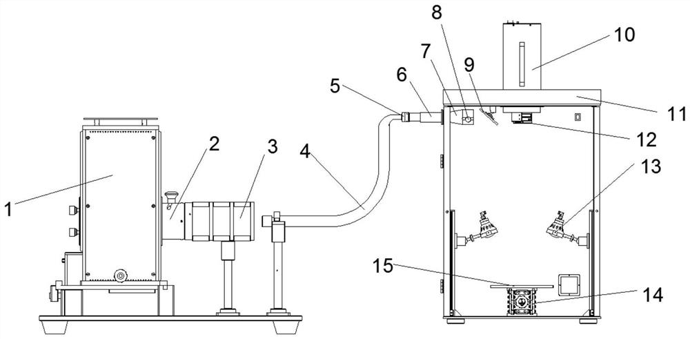
[0033] A fluorescent hyperspectral testing system provided by a preferred embodiment of the present invention includes a sample box 11 and a light source, the light source includes a xenon light source 1 and a halogen light source 13, the xenon light source 1 is located outside the sample box 11, and the halogen light source 13 is located on the inner wall of the sample box 11; the top in the sample box 11 is provided with a hyperspectral camera 10, the hyperspectral camera 10 is connected with an emission filter set 12, and the bottom of the sample box 11 is provided with a sample stage 15; the sample box 11 is provided with a reflector 9 and a first angle adjustment bracket, and the reflector 9 is fixed on the top of the sample box 11 by the first angle adjustment bracket; it also includes an optical waveguide 4 and a uniform light device, the The homogenization device includes a first focusing lens 2, a second focusing lens 7, a light pipe 6, and an excitation filter group 5...

Embodiment 2

[0041] In this embodiment, on the basis of Embodiment 1, a heat insulating device 3 is provided between the light outlet of the xenon lamp light source 1 and the light inlet of the optical waveguide 4. Preferably, the heat insulating device 3 consists of several heat insulating sheets Arrange composition.

[0042] Specifically, because the energy of the spectrum emitted by the xenon lamp light source 1 is different under different wavelengths, the closer to the infrared band, the higher the heat, and the level of light intensity and energy will cause certain damage to the sample, detector, etc. The heat device 3 partially weakens the light intensity and energy, and can increase the number of heat shields according to the needs of the actual situation to achieve a good heat insulation effect.

Embodiment 3

[0044] In this embodiment, on the basis of the first embodiment, the second focusing lens 7 is provided with a focusing knob 8 .

[0045] Specifically, the user can adjust the focal length of the second focusing lens 7 through the focusing knob 8 according to actual needs.


PUM


Abstract

The invention discloses a fluorescent hyperspectral testing system, which belongs to the technical field of hyperspectral testing and relates to a fluorescent hyperspectral testing system. In the fluorescent hyperspectral testing system of the present invention, the light passes through the first focusing lens, the optical waveguide, the excitation filter group, the light guide tube, the second focusing lens, the reflection mirror, the sample stage, and the emission filter group in sequence, Finally, it is captured by a hyperspectral camera, which can provide a large area of ​​irradiation spot for fluorescence hyperspectral imaging, and make the light irradiate evenly on the sample, increasing the imaging effect, and avoiding the problem of damage caused by the incident light directly irradiating the sample, and The optical path does not affect each other, which improves the accuracy of detection; it can also quickly complete the switching between the xenon light source and the halogen light source, which improves the work efficiency.

Description

technical field [0001] The invention belongs to the technical field of hyperspectral testing and relates to a fluorescent hyperspectral testing system. Background technique [0002] Hyperspectral imaging technology is an image data technology based on very narrow bands developed in the past two decades. Its most prominent application is in the field of remote sensing detection, and it has greater application prospects in more and more civilian fields. [0003] The definition of hyperspectral imaging technology is based on multispectral imaging, in the spectral range from ultraviolet to near infrared (200-2500nm), using imaging spectrometers, dozens or hundreds of spectral bands within the spectral coverage The target object is continuously imaged. While obtaining the spatial feature imaging of the object, the spectral information of the measured object is also obtained. Hyperspectral imager (also known as spectral camera or hyperspectral camera, hyperspectrometer) is a non...

Claims


Application Information

Patent Timeline
Patent Type & Authority Patents(China)
IPC IPC(8): G01J3/44G01J3/02
CPCG01J3/4406G01J3/0208
Inventor 陈兴海刘业林黄智辉黄宇王金龙于金科
Owner SICHUAN DUALIX SPECTRAL IMAGING TECHNOLOGY CO LTD
Why Eureka
Try Eureka