[0012]The present invention has been made in consideration of such problems, and an objective of the present invention is to provide a torque sensor having a high temperature drift compensation and including a
failure diagnosis function in a simple configuration. The present invention intends to provide a torque sensor that contributes to an accurate failure diagnosis based on both AC phase component and DC voltage component, particularly a torque sensor that enables transmission of failure
diagnostic information based on the DC voltage component with less transmission lines. Further, the present invention intends to provide a torque sensor that has a configuration in which the
dynamic range of a detection output signal can be widened, thereby improving the detection accuracy.
[0016]As described above, the present invention advantageously allows a single differential signal output from the
differential amplifier circuit to contain all of the torque detection information, information about the failure appearing as a fluctuation of the DC component, and information about the failure appearing as a fluctuation of the phase component. Accordingly, the present invention has an excellent effect that the torque detection information and all necessary failure information can be transmitted via single output line of a highly simplified line configuration. Notwithstanding, the torque sensor has an advanced failure diagnostic function. Further, as described above, the
differential amplifier circuit provides the torque detection signal having an expanded
dynamic range, resulting in a torque sensor with improved detection accuracy. Moreover, the torque sensor includes the temperature characteristic compensation
resistor element connected with the coil, thus allowing formation of the coil output signal which has undergone temperature drift compensation. This also results in the torque sensor with improved detection accuracy.
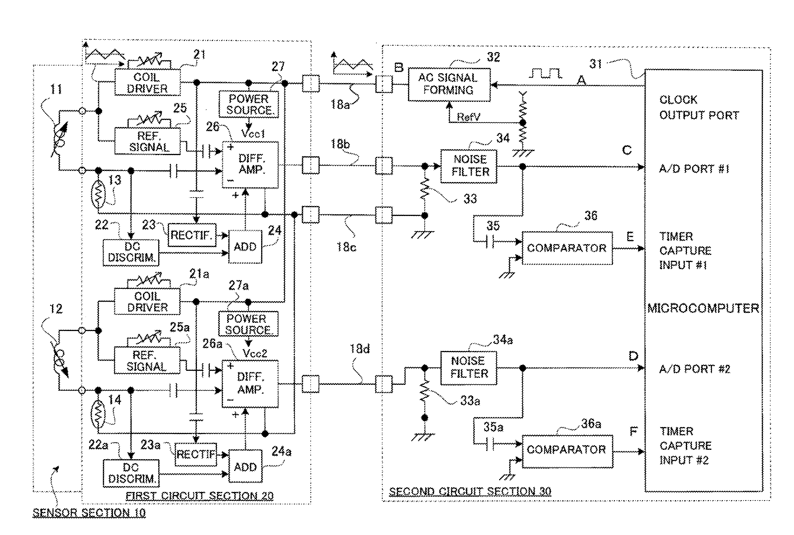
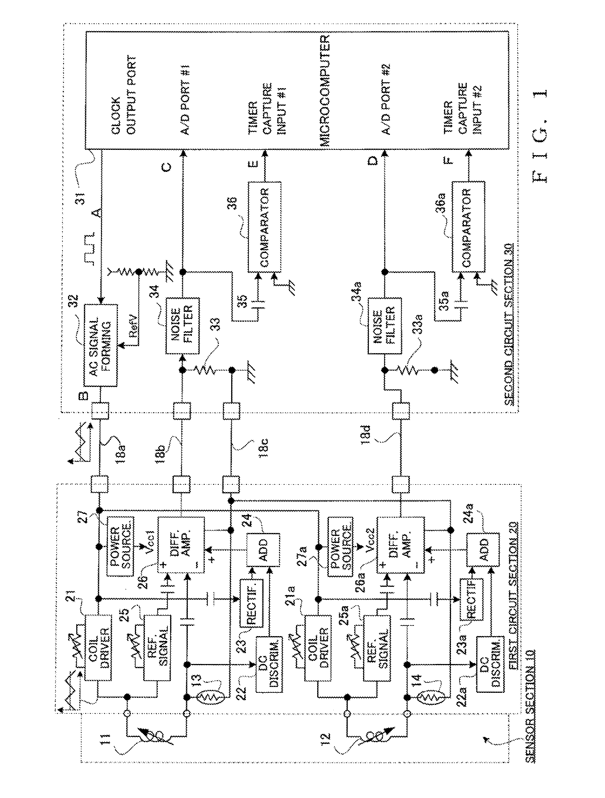
[0018]Accordingly, the casing containing the sensor section houses the first circuit section that includes the temperature characteristic compensation
resistor element, the coil
driver circuit, the offset voltage generating circuit, and the differential
amplifier circuit. This allows an arrangement of parts where the torque detection information and all the necessary failure information can be transmitted from the sensor section side with the single output line as described above. Therefore, the present invention has an excellent effect that during such operation a separate power source line is not required for the first circuit section on the sensor section side. In other words, the excitation AC signal fed by the
single excitation AC signal feeding line contains the power source DC voltage added thereto. Accordingly, the first circuit section on the sensor section side can extract the predetermined DC voltage contained in the excitation AC signal to use it as a DC power source for each of the circuits housed in the casing side section. Therefore, according to this embodiment, a separate DC power source feeding line is not necessary, thus simplifying the
transmission line between the first circuit section and the second circuit section.
[0020]In a preferable embodiment, the sensor section may include first and second coils. The first and the second
magnetism-responsive members may be configured and the first and the second coils may be placed such that the first and the second coils have impedance changes inverse to each other in response to the relative rotational position of the first and the second rotational shafts. The first and second coils may be provided with the respective temperature characteristic compensation
resistor elements, the coil driver circuits, the offset voltage generating circuits, and the differential
amplifier circuits. The torque detection section may detect the amplitude of the AC component in the differential signal output from thedifferential
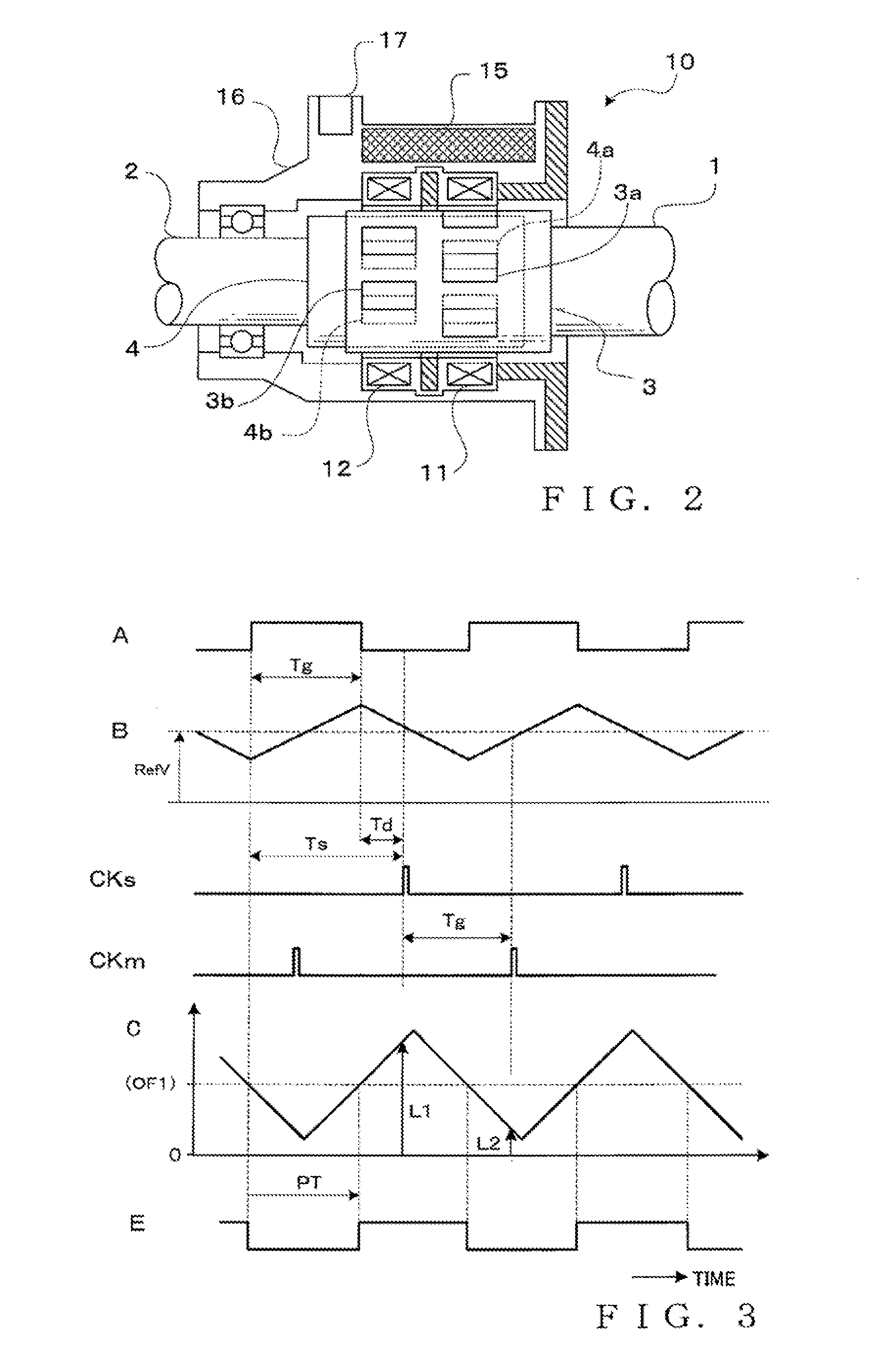
amplifier circuit corresponding to the first coil to obtain a detection data in response to the impedance change of the first coil as a first torque detection data and may detect the amplitude of the AC component in the differential signal output from the differential amplifier circuit corresponding to the second coil to obtain a detection data in response to the impedance change of the second coil as a second torque detection data. The offset voltage extraction section may extract a voltage corresponding to a center of the amplitude of the AC component of the differential signal output from the differential amplifier circuit corresponding to the first coil as a first offset voltage and may extract a voltage corresponding to a center of the amplitude of the AC component of the differential signal output from the differential amplifier circuit corresponding to the second coil as a second offset voltage. The failure diagnostic section may determine that
abnormality is present if at least one of the first and the second offset voltages falls out of a predetermined range. Another failure diagnostic section may be provided which determines that a
normal state is retained if a value resulting from an addition of the first and the second torque detection data falls within a predetermined range and that
abnormality is present if the value resulting from the addition falls out of the predetermined range. This allows for formation of two kinds of detection signals having characteristics inverse to each other with respect to the relative rotational position (torque), thereby enabling a sensor having redundancy which is considered to be necessary for improved safety of a torque sensor for a
power steering shaft of an automobile.

