
Plasterboard Jointing System

a jointing system and plasterboard technology, applied in lamination, mechanical control devices, structural elements, etc., can solve the problems of incomplete setting, affecting the strength of the joint, waste of products, etc., and achieve the effect of reducing installation delays and shrinkag

Inactive Publication Date: 2012-02-09
CSR BUILDING PRODUCTS LTD
View PDF4 Cites 23 Cited by
  • Summary
  • Abstract
  • Description
  • Claims
  • Application Information

AI Technical Summary

Benefits of technology

[0035]According to a preferred feature of the present invention the connective material is a plaster-based compound with a moderate wet and high dry compressive strength and a short setting time. Preferably, the high compressive strength may be approximately 9 MPa and the short setting time may be approximately 45 min.
[0046]According to a preferred feature of the present invention each of the plasterboard sheets has a notched side edge portion and the connective material is a plaster-based compound with a moderate wet high compressive strength and a short curing time. In this case, the high compressive strength may be approximately 9 MPa and the short curing time is approximately 45 min.
[0054]According to a preferred feature of the present invention the finishing compound is able to be readily applied by a trowel and is subject to shrinkage of less than 15%. If so, then the finishing compound may preferably be subject to shrinkage of 10% or less. According to another preferred feature of the present invention the finishing compound may contain glass microspheres.

Problems solved by technology

Conventional jointing and finishing of plasterboard sheets utilises a relatively complicated and time consuming process.
Incomplete setting compromises the strength of the joint.
Short setting time can result in product being wasted.
For example, when setting type compounds are used during hot, dry conditions, rapid evaporation of water and increased absorption by the lining surface can prevent the compound from setting correctly.
This will result in the compound being soft and weak.
As can be appreciated, the conventional process for jointing and finishing of plasterboard sheets is relatively complicated, time consuming and requires a relatively skilled installer to achieve a joint of sufficient integrity and suitable level of finish achieving a desirable aesthetic appearance.

Method used


Image

  • Plasterboard Jointing System
  • Plasterboard Jointing System
  • Plasterboard Jointing System

Examples


example 1

Use of Alpha Gypsum Hemihydrate Connective Material

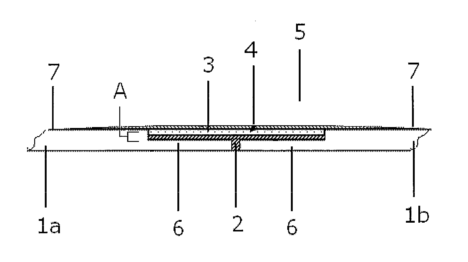
[0120]The side edges of two plasterboards 1a, 1b were abutted together and a connective material 2 was applied as a first layer in the recess 5. The connective material 2 was formulated using the following compounds:[0121]95.30% w / w Alpha plaster (Hydrostone TB);[0122]0.10% w / w Calcium hydroxide (hydrated lime);[0123]1.00% w / w PVAL (polyvinyl alcohol);[0124]2.00% w / w EVA powder;[0125]0.30% w / w Sorbitol;[0126]0.20% w / w Modified cell ether (methyl cellulose, such as the proprietary product “Mecellose™ FMC 7150”, manufactured and sold by Samsung Fine Chemicals Co, Ltd of South Korea);[0127]0.05% w / w SMA; and[0128]1.00% w / w 3 mm length fibreglass strands

[0129]After the connective material 2 was applied to the recess 5, it was allowed to cure for 45 min. Once the connective material 2 was sufficiently cured, a joint filling compound 3 was applied to the recess over the connective material. The joint filling compound 3 was spread out usin...

example 2

Use of Plaster Coated Reinforcing Mesh Connective Material with Pre-Wet Technique

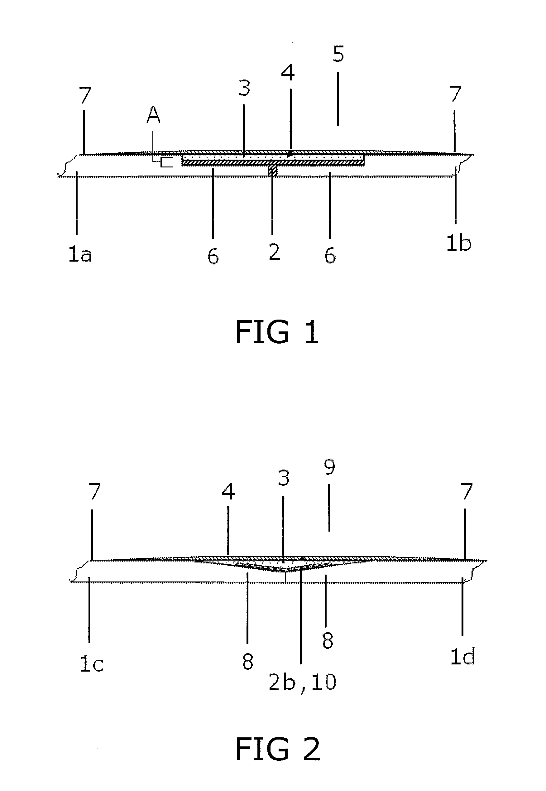
[0131]The side edges of two plasterboards 1c, 1d were abutted together and a connective material 2b was applied as a first layer in the recess 9. The connective material 2b was a proprietary bandage, Gypsona™ Extra 3, which is manufactured and sold by BSN Medical SAS of Vibraye, France.

[0132]In one example, water, which is a reactive element or catalyst, was initially applied with a damp sponge and / or water brush to the recessed edge portion 9 of both of the side edges of the two plasterboards 1c, 1d. In a second trial, water, which is a reactive element or catalyst, was initially applied with a damp sponge and / or water brush to the underside of the Gypsona™ Extra 3 plaster coated reinforcing mesh 10. In both trials, after the water had been applied, the Gypsona™ Extra 3 plaster coated reinforcing mesh 10 was then applied as a first layer in the recess 9.

[0133]After the connective material 2b was applie...

example 3

Use of Self Adhesive Plaster Coated Reinforcing Mesh Connective Material

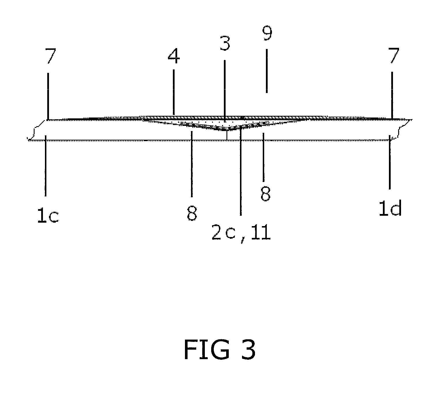
[0135]The side edges of two plasterboards 1c, 1d were abutted together and a connective material 2b was applied as a first layer in the recess 9. The connective material 2b was a proprietary bandage, Gypsona™ Extra 3, which is manufactured and sold by BSN Medical SAS of Vibraye, France. The Gypsona™ Extra 3 bandage was initially coated with a spray adhesive, HB Fuller Spray Bond Removable clear spray adhesive.

[0136]The connective material 2b was applied to the recess 9 by sticking the bandage to the recess by way of the spray adhesive coating. After the connective material 2b was applied to the recess 9, a joint filling compound 3 was applied to the recess over the connective material. The joint filling compound 3 was spread out using a trowel or some other suitable implement to create a substantially smooth finish. Finally, a finishing compound 4 was then applied over the joint filling compound, which was initi...


PUM

PropertyMeasurementUnit
compressive strengthaaaaaaaaaa
lengthaaaaaaaaaa
shrinkageaaaaaaaaaa

Abstract

The present invention provides a system of jointing and finishing plasterboard sheets. The system comprises adjacently abutted first and second plasterboard sheets and a connective material. The connective material is applied to a region at or near the side edge portions of the first and second plasterboard sheets and which securely joins the side edge portion of the first plasterboard sheet to the side edge portion of the second plasterboard sheet. There is also provided a joint filling compound and a finishing compound, which are optionally also applied to the region of the first and second plasterboard sheets.

Description

PREVIOUS APPLICATION[0001]The present application is a continuation of an International Patent Application No. PCT / AU2010 / 000202 designation the USA, with an International Application date of 23 Feb. 2010, and published as WO 2010 / 099563.TECHNICAL FIELD[0002]The present invention relates to a system of jointing and finishing plasterboard sheets. Particularly, the present invention relates to a system that reduces the cost of site labour, reduces the number of steps involved in jointing and finishing the plasterboard sheets, reduces the time required to perform each of these steps and overall improves the efficiency of jointing and finishing plasterboard sheets.BACKGROUND TO THE INVENTION[0003]Conventional jointing and finishing of plasterboard sheets utilises a relatively complicated and time consuming process. Conventional jointing and finishing of plasterboard interior installations is typically carried out in accordance with table 1 shown below, and the following details, so as t...

Claims


Application Information

Patent Timeline
Patent Type & Authority Applications(United States)
IPC IPC(8): B32B37/02B32B37/14B32B37/12
CPCC04B28/146C04B2111/00482C04B2111/00672C04B2111/34E04F13/04E04F13/042C04B20/0048C04B40/0641C04B41/4803C04B14/42
Inventor THOMPSON, BILLLAVENDER, DOUGGALE, EDWARD
Owner CSR BUILDING PRODUCTS LTD
Learn More