Semiconductor device driving unit and method

a technology of semiconductor devices and driving units, applied in the direction of pulse generators, pulse techniques, electric pulse generator circuits, etc., can solve the problems of increasing the breakdown voltage, increasing the igbts, and ensuring a wide installation space, so as to suppress the increase of switching loss and reduce the surge voltage

Active Publication Date: 2012-02-09
HONDA MOTOR CO LTD
View PDF4 Cites 13 Cited by
  • Summary
  • Abstract
  • Description
  • Claims
  • Application Information

AI Technical Summary

Benefits of technology

[0025]One or more embodiments of the invention provide a unit and a method for driving a semiconductor device having a switching function which can reduce a surge voltage while suppressing increase of a switching loss when the semiconductor device is switched.

Problems solved by technology

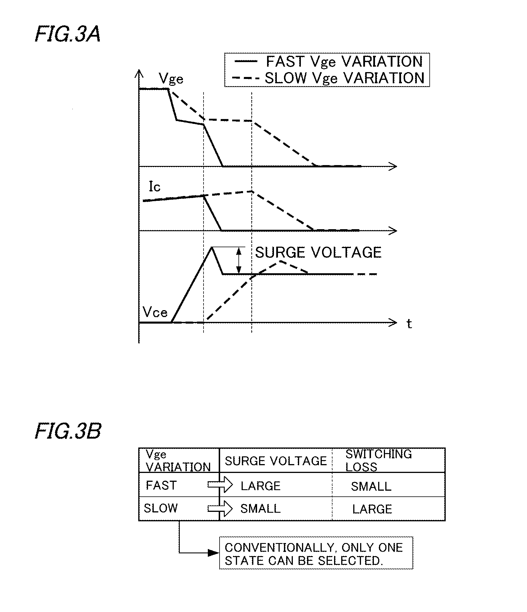
However, a surge voltage occurs in a transient period of switching such as turn-on or turn-off of the IGBT.
Therefore, naturally, as the surge voltage becomes higher, the required breakdown voltage increases and IGBTs become larger.
However, in the case of electric vehicle inverters, it is difficult secure a wide installation space in an electric vehicle and hence it is very difficult to employ large IGBTs.
However, lowering the switching speed to reduce the surge voltage results in increase in the loss (hereinafter referred to as a switching loss) of the IGBT and the FWD in a switching transient period.
Although patent documents 1-3 disclose several techniques for satisfying this demand, it cannot be said that any of these techniques are satisfactory.

Method used


Image

  • Semiconductor device driving unit and method
  • Semiconductor device driving unit and method
  • Semiconductor device driving unit and method

Examples


Embodiment Construction

[0051]Embodiments of the present invention will be hereinafter described with reference to the drawings.

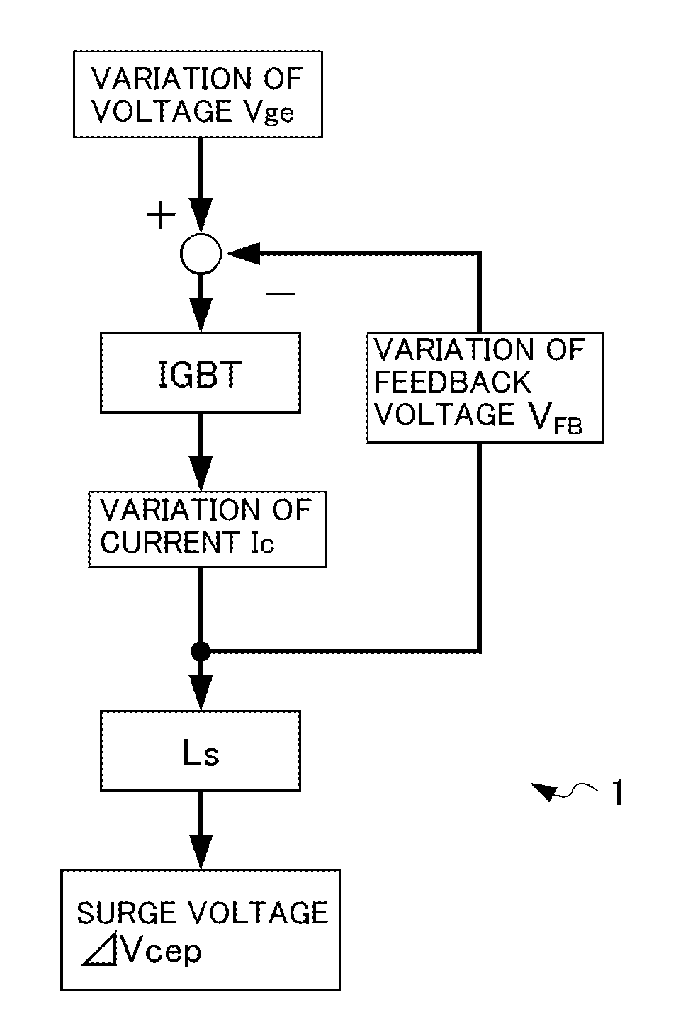
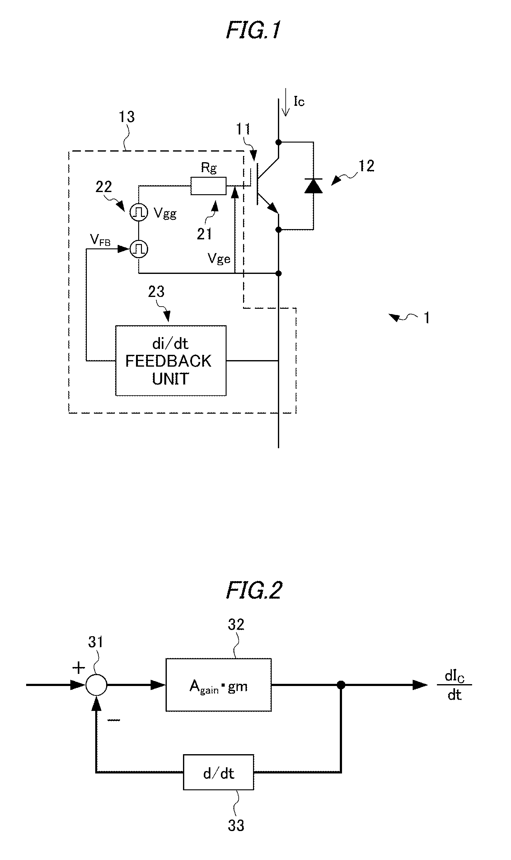
[0052]FIG. 1 shows a general configuration of an electronic circuit 1 including a semiconductor device drive circuit 13 according to an embodiment.

[0053]For example, the electronic circuit 1 can be used as part of a power module of an electric vehicle inverter. The electronic circuit 1 is equipped with an IGBT 11, an FWD 12, and the semiconductor device drive circuit 13.

[0054]The IGBT 11 and the FWD 12 are connected to each other in parallel in such a manner that their input / output directions are opposite to each other.

[0055]The IGBT 11 has a switching function of causing connection or disconnection of a bus such as an inverter power line, and is turned on or off according to the magnitude of the voltage of a drive signal supplied to its gate, that is, the magnitude of its gate-emitter voltage Vge.

[0056]That is, the semiconductor device drive circuit 13 controls turn-on and turn-o...


PUM


Abstract

A turn-off feedback unit (23OFF) of a semiconductor device driving unit generates a feedback voltage as part of a voltage of a drive signal for establishing electrical continuity or disconnection in a bus according to a temporal variation of a collector current of a first semiconductor device (11U) when the first semiconductor device (11U) is turned off from on. A turn-on feedback unit (23ON) generates the feedback voltage according to a commutation current flowing through a free wheeling diode (12D) connected to a second semiconductor device (11D) when the first semiconductor device (11U) is turned on from off.

Description

BACKGROUND OF THE INVENTION[0001]1. Field of the Invention[0002]The present invention relates to a unit and a method for driving a semiconductor device having a switching function. More specifically, the invention relates to a semiconductor device driving unit and method which can reduce a surge voltage while suppressing increase of a switching loss when the semiconductor device is switched.[0003]2. Related Art[0004]Conventionally, electric vehicles generally employ a synchronous motor which is driven by three-phase AC voltages. Therefore, electric vehicles incorporate an inverter which drives the synchronous motor by converting a DC output voltage of a battery (DC power source) into three-phase AC voltages. An inverter that is incorporated in an electric vehicle is expressly called an electric vehicle inverter.[0005]Many electric vehicle inverters employ PWM (pulse width modulation) control and employ an IGBT (insulated gate bipolar transistor) as a power semiconductor device for r...

Claims


Application Information

Patent Timeline
Patent Type & Authority Applications(United States)
IPC IPC(8): H03K3/30
CPCH02M1/44H03K17/04206H03K17/0424H03K17/168H03K17/166
Inventor SAOTOME, KOJITSUKADA, YOSHINARIGOTO, MASATOSHITAKEUCHI, YUSUKE
Owner HONDA MOTOR CO LTD
Why Eureka
Try Eureka