Infusion Pump and Slide Clamp Apparatus and Method

a technology of infusion pump and slide clamp, which is applied in the direction of suction device, intravenous device, other medical devices, etc., can solve the problems of not having the degree of precision in fluid delivery that is typically required, not having a fully reliable metering device, and using a ramp valve that does not provide the degree of fluid delivery precision that is needed, etc., to prevent the free flow of fluid and achieve anti-free flow functionality

a technology of infusion pump and slide clamp, which is applied in the direction of suction device, intravenous device, other medical devices, etc., can solve the problems of not having the degree of precision in fluid delivery that is typically required, not having a fully reliable metering device, and using a ramp valve that does not provide the degree of fluid delivery precision that is needed, etc., to prevent the free flow of fluid and achieve anti-free flow functionality

US20120035581A1Inactive Publication Date: 2012-02-09WALKMED INFUSION

Image

  • Infusion Pump and Slide Clamp Apparatus and Method
  • Infusion Pump and Slide Clamp Apparatus and Method
  • Infusion Pump and Slide Clamp Apparatus and Method

Examples


Embodiment Construction

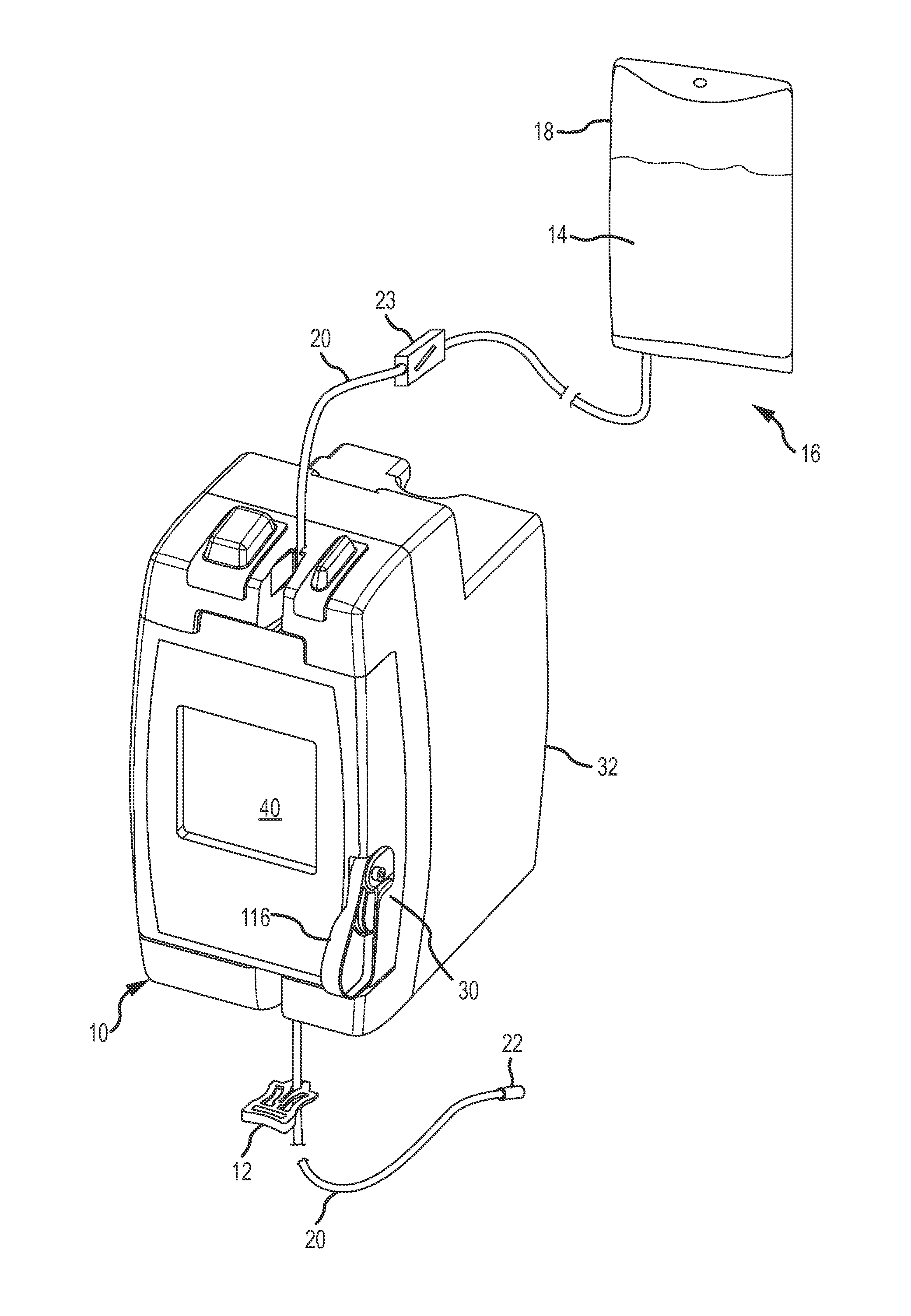
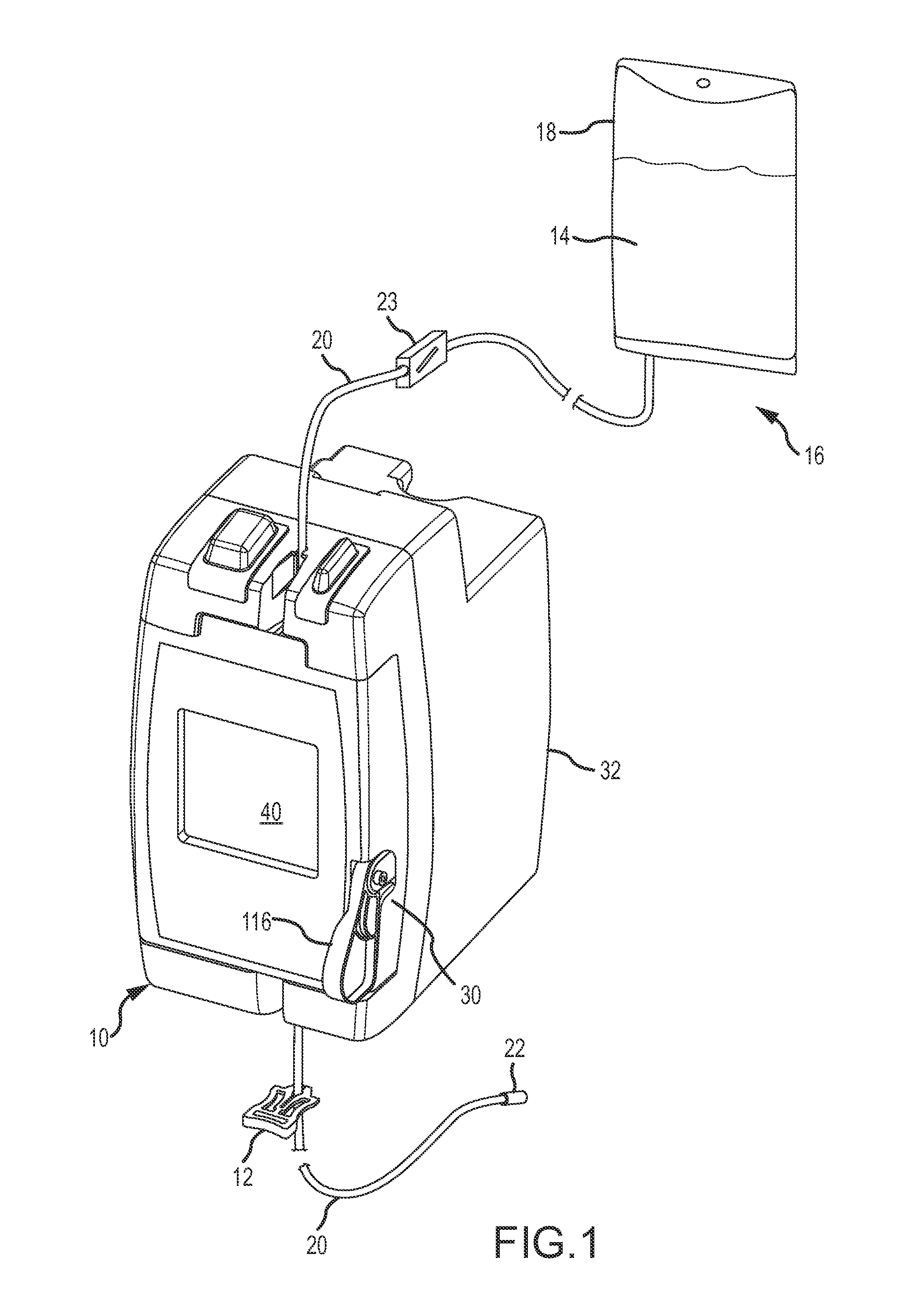
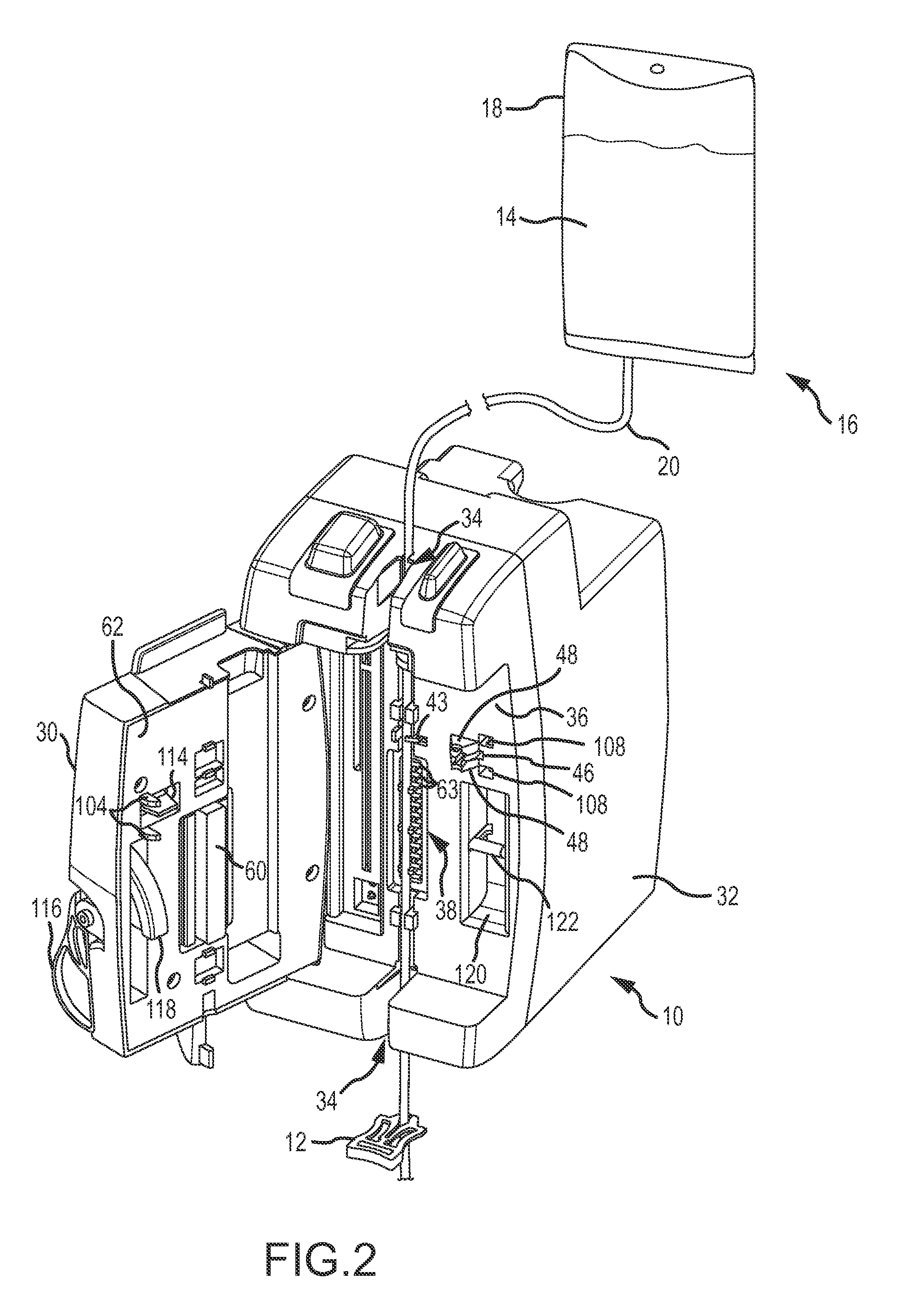
[0034]An infusion pump 10 and a slide clamp 12 which embody the present invention are shown in FIG. 1. The infusion pump 10 precisely meters a flow of medicinal fluid 14 through an intravenous tubing set 16 to a patient (not shown). The tubing set 16 includes a flexible and collapsible bag 18 which stores the fluid 14, and a delivery tube 20 which conducts the fluid 14 from the bag 18 to a connector 22. The connector 22 connects to a needle (not shown) inserted into a vessel, typically a vein of a patient, or to a complementary connection of a conventional vessel access device attached to the patient. A conventional ramp or roller clamp 23 is connected to the delivery tube 20 to constrict the delivery tube 20 and thereby control the cross-sectional size of an opening through the delivery tube through which the fluid 14 flows. The roller clamp 23 will typically be moved to a non-restricting position when the infusion pump 10 is in operation, because the infusion pump meters the flow ...


PUM


Abstract

An infusion pump for metering fluid flow through an delivery tube of an infusion tubing set has an internal occlusion clamp which clamps the delivery tube to prevent the free flow of fluid through the tube when access to the delivery tube in the infusion pump is possible. To release the delivery tube from the infusion pump, a slide clamp is manually used to release the occlusion clamp to an open, non-occluding position while simultaneously occluding the delivery tube to prevent the free flow of fluid.

Description

[0001]This invention relates to prohibiting the free flow of medicinal fluid into a patient from a delivery tube of an intravenous tubing set used with an infusion pump. More particularly, the present invention relates to a new and improved apparatus and method which uses a slide clamp to release the delivery tube from the infusion pump and simultaneously occlude a delivery tube, thereby ensuring that the delivery tube is occluded whenever the delivery tube is removed from the infusion pump.BACKGROUND OF THE INVENTION[0002]Intravenous tubing sets are commonly used with an infusion pump to deliver fluid medications directly into the bloodstream of a patient. Fluid, such as glucose or saline, is mixed or dissolved with a medical substance in a bag, and a delivery tube conducts the medicinal fluid from the bag into a needle or other connector which delivers the fluid into a vessel, typically a vein, of the patient. The bag is suspended above the patient so that the force of gravity act...

Claims


Application Information

Patent Timeline
09 Feb 2012
Publication
US20120035581A1
IPC
A61M5/142; A61M39/28
CPC
A61M39/28; A61M5/16813; A61M39/287
Inventors
TRAVIS, LEE W.