

Combustion apparatus, method for combustion control, combustion control board, combustion control system and water heater
a combustion apparatus and combustion control technology, applied in the direction of combustion failure safe, lighting and heating apparatus, fluid heaters, etc., can solve the problems of difficult to apply the art to the equipment for an extended exhaust pipe, reduce heat efficiency, and not be suitable for outdoor installation. , to achieve the effect of minimizing the apparatus
- Summary
- Abstract
- Description
- Claims
- Application Information
AI Technical Summary
Benefits of technology
Problems solved by technology
Method used
Image

Examples
first embodiment
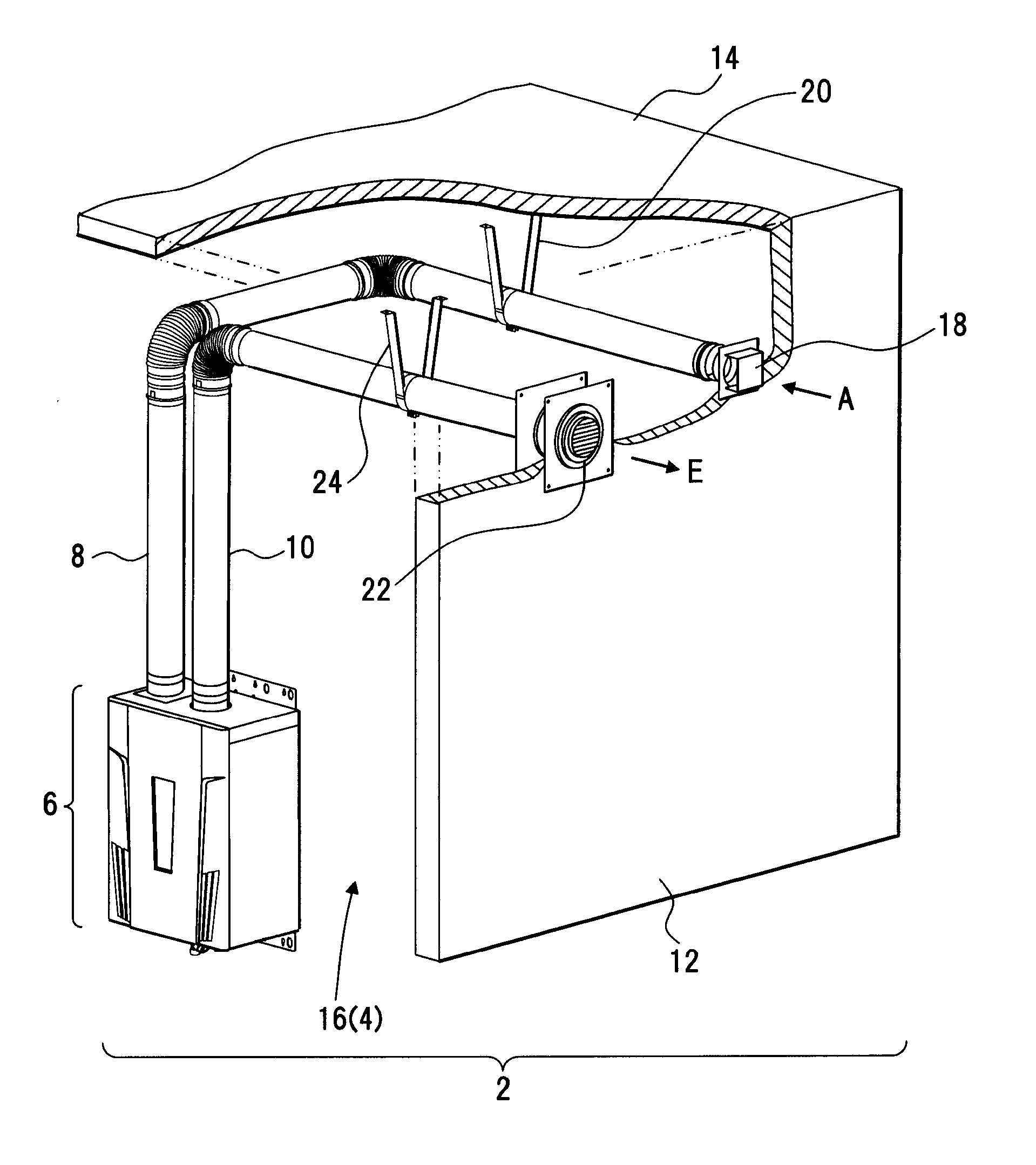
[0039]A first embodiment discloses a water heating system. The first embodiment will be described with reference to FIG. 1. FIG. 1 depicts an example of a water heating system.
[0040]A water heating system 2 is an example of a combustion apparatus, a method for combustion control, a combustion control board, a combustion control system or a water heater of the present invention. The water heating system 2 is installed in a room 4, and, as depicted in FIG. 1, provides a water heater 6, an air supply path 8 and an exhaust path 10.
[0041]The water heating system 2 is an example of a combustion system combusting fuel gas G. The water heating system 2 is a system for exchanging heat of combustion exhaust for water to supply the heated water.
[0042]The room 4 is an example of a room separated from a living space, and may be a space closed to the outside air such as a garage. A wall 12 and a ceiling 14 are separation means separating the water heating system 2 from the outside air. 16 is an i...
second embodiment
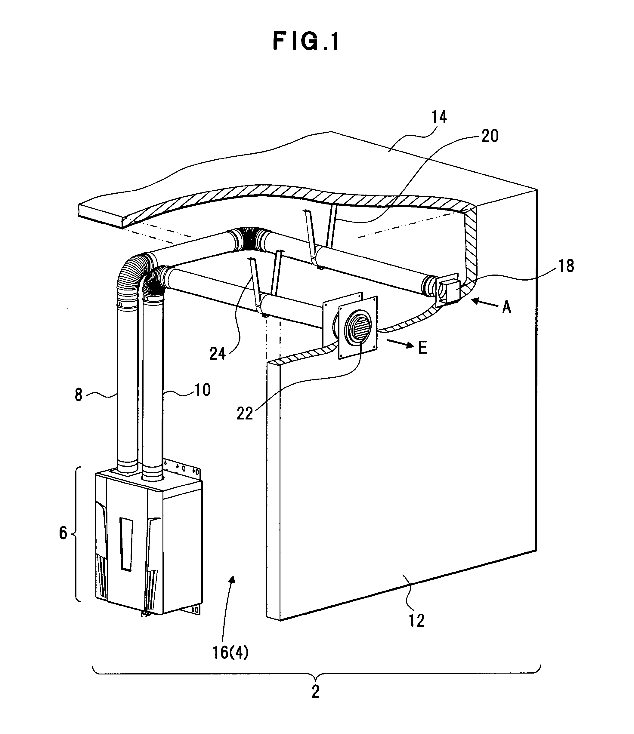
[0048]A second embodiment discloses the above described water heater 6. The second embodiment will be described with reference to FIGS. 2 and 3. FIG. 2 depicts an example of a water heater and FIG. 3 depicts an enlarged combustion chamber of the water heater.
[0049]The water heater 6 is an example of a combustion apparatus of the present invention. The water heater 6 exchanges heat of combustion exhaust for water W to supply hot water HW. A housing 26 is provided for the water heater 6. A combustion chamber 28 is placed in the housing 26. The housing 26 is a sealed space. An air supply tube 30 is formed on the housing 26 for supplying air into the sealed space. The above described air supply path 8 is connected to the air supply tube 30, and air supply A is executed via the air supply tube 30 and the air supply path 8.
[0050]The combustion chamber 28 is a combustion space. An exhaust dilution unit 32 is provided for the combustion chamber 28 on its top. An exhaust tube 34 is formed on...
third embodiment
[0150]In the second embodiment, the control of the exhaust temperature is disclosed that the combustion is reduced to lower the temperature of the combustion exhaust E. This third embodiment discloses that the temperature of the combustion exhaust E is lowered by dilution air from the exhaust dilution fan 100.
[0151]The third embodiment will be described with reference to FIG. 10. FIG. 10 depicts an example of processing procedure of an exhaust temperature control process according to the third embodiment.
[0152]The processing procedure is an example of the present invention, and includes a process that the rotation speed of the exhaust dilution fan 100 is increased maintaining the volume of the combustion, and dilution air is increased to lower the exhaust temperature. The processing procedure is executed in the above described water heater 6. In the processing procedure, as depicted in FIG. 10, it is determined whether the detected temperature of the combustion exhaust E is equal to...
PUM
 Abstract
Description
Claims
Application Information