Synchronous Induced Wind Power Generation System

a technology of synchronous induced wind power and wind power, which is applied in the direction of electric generator control, machines/engines, mechanical equipment, etc., can solve the problems of inability to achieve large-scale adoption of wind power as an alternative means, difficulty in repair and maintenance of large systems, and limited effect of conventional wind power generation systems

Inactive Publication Date: 2012-02-16
SKALA JAMES A
View PDF0 Cites 30 Cited by
  • Summary
  • Abstract
  • Description
  • Claims
  • Application Information

AI Technical Summary

Benefits of technology

[0030]The permanent magnets are preferably capable of providing braking power equivalent to the maximum rated wind speed of the system, such that with the permanent magnets in place, the system will not be damaged by winds up to the maximum wind rating with the generator off line and unattended. Further, the turbine-generator section aligns itself with the prevailing wind direction by wind vane action, with rotation about a pivot on a central pedestal, and is preferably supported by wheels on a circular track that surrounds the entire device.
[0031]The pitch of the directrix blading is preferably capable of being adjusted to both increase or decrease the torque output of the turbine, and in the case of severely high wind speeds, to reduce the turbine torque to near zero when needed, thus allowing wind to pass through the turbine without taking much energy from it when the unit is disconnected from the load. The

Problems solved by technology

However, the effectiveness of conventional wind power generation systems have been limited by various difficulties such as, for example, the inconsistency of the wind, appropriate locations for placement of wind power generation system far from load centers and the problems of long distance transmission of power, difficulty in repair and maintenance of large systems, etc.
These difficulties have inhibited large scale adoption of wind power as an alternate means of energy.
However, the longer blades require a supporting tower having a corresponding increased height and size.
Further, such large size blades prevent placement of convention

Method used


Image

  • Synchronous Induced Wind Power Generation System
  • Synchronous Induced Wind Power Generation System
  • Synchronous Induced Wind Power Generation System

Examples


Embodiment Construction

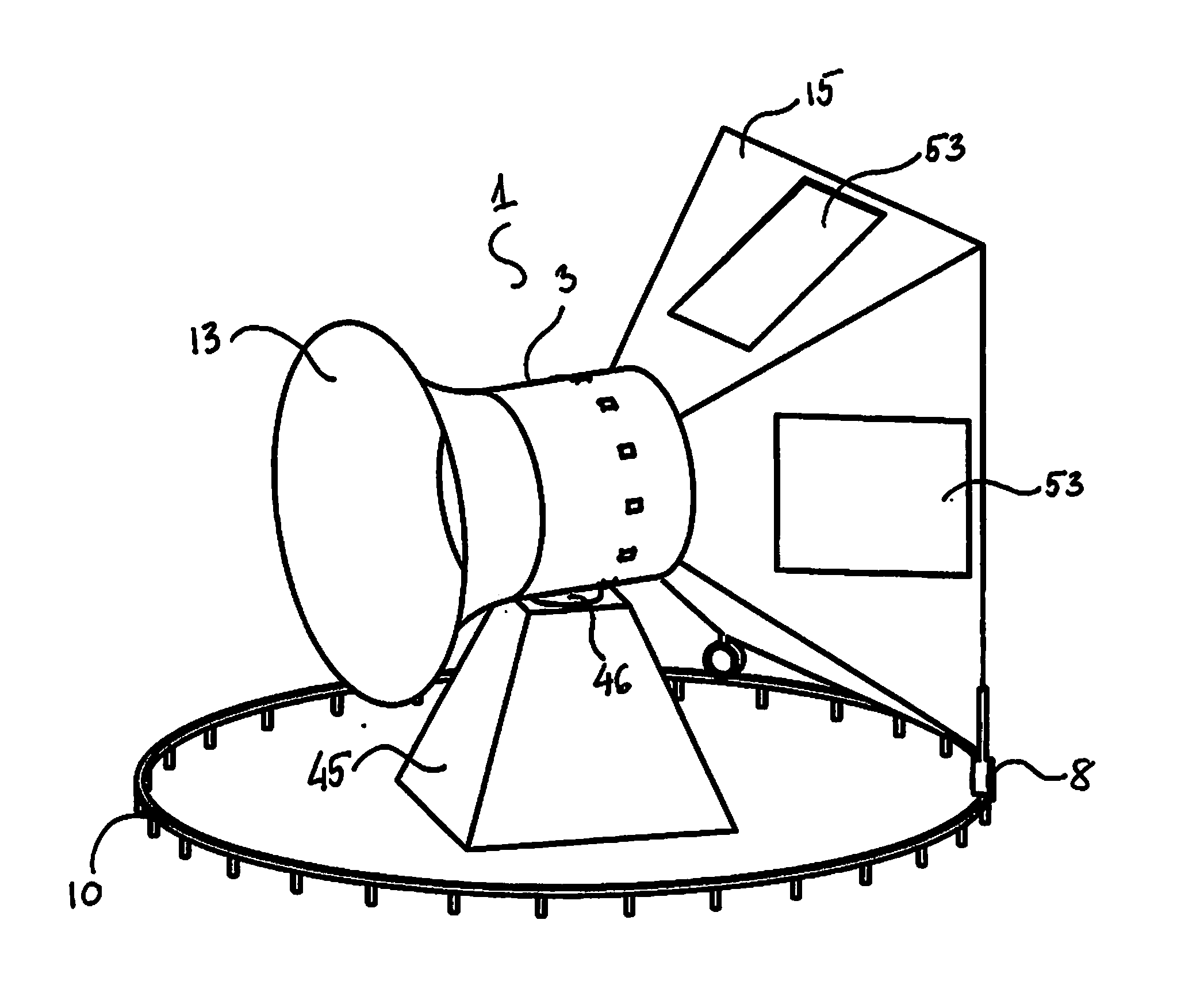
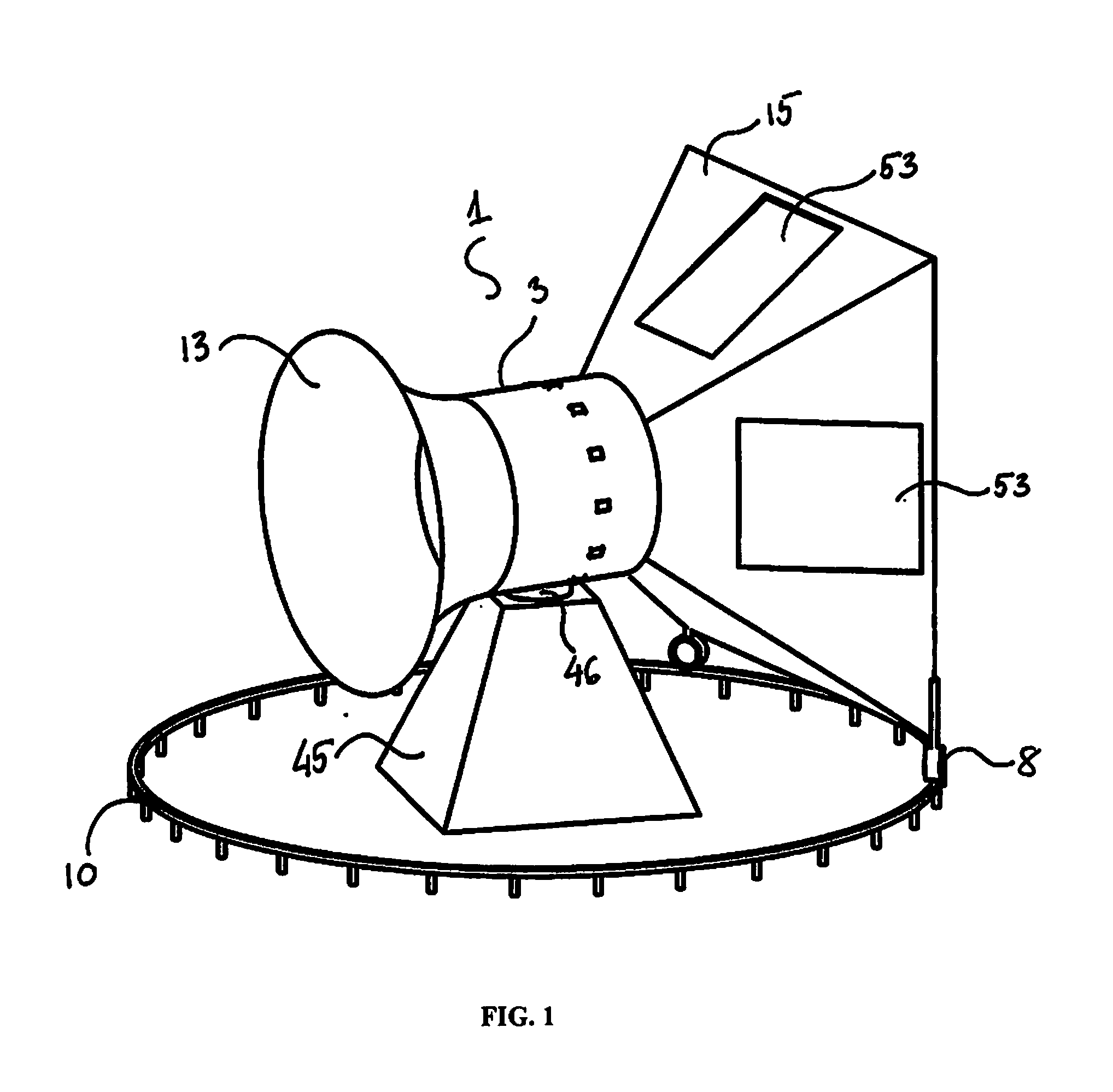
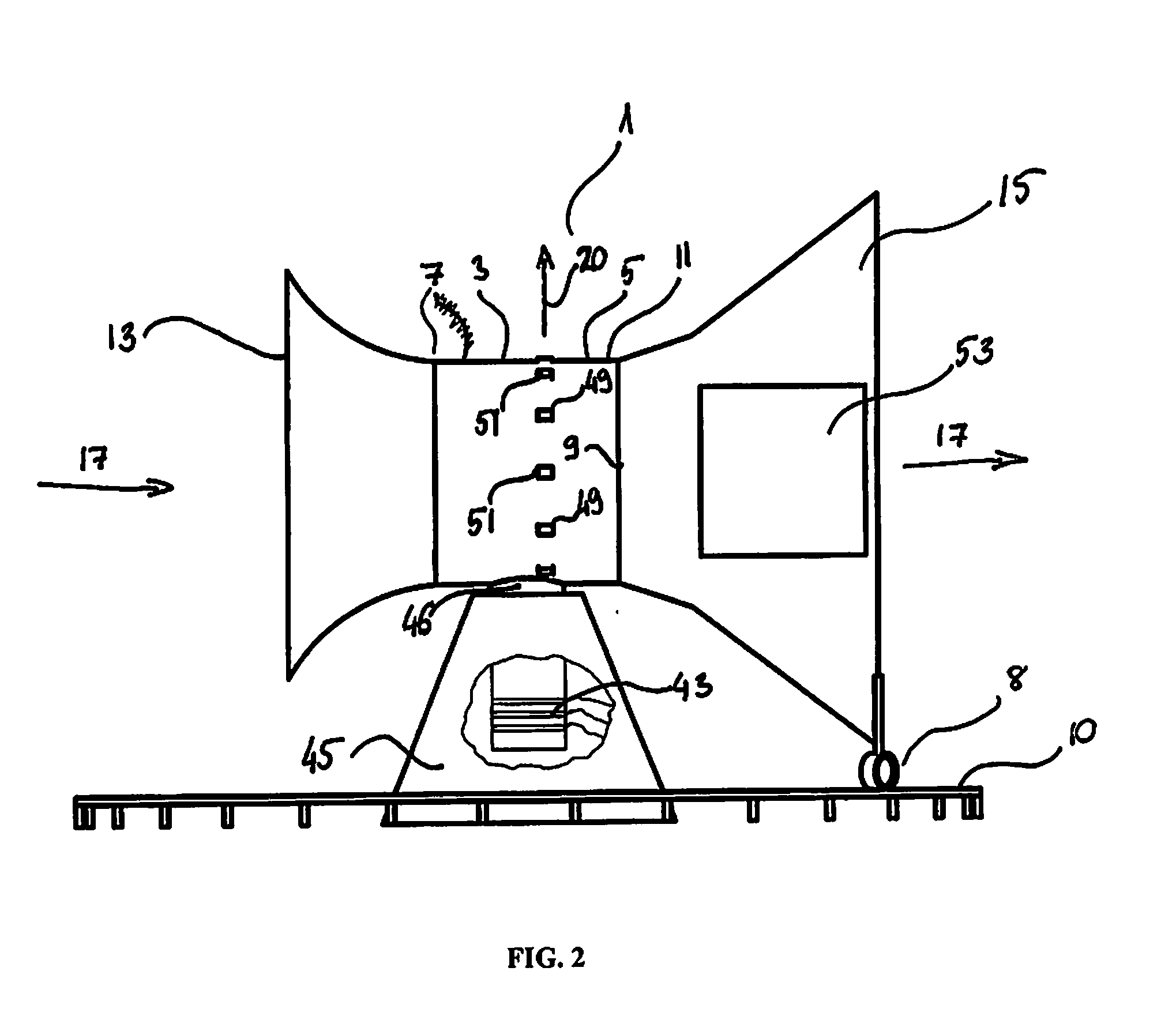
[0050]As illustrated in FIGS. 1-3, a synchronous induced wind power generation system 1 is provided that may be conveniently deployed in urban environments, such as on the tops of flat roofed buildings. In fact, this abundantly available urban area is one of the most advantageous locations for placement due to the higher ambient winds flowing over the roof caused by the building itself. Advantageously, elements of the system 1 are operable to limit the maximum stress applied to the building on which the system 1 is mounted, such that the force applied against the building does not rise with the cube of wind speed after the unit reaches 100% power, as might otherwise be expected.

[0051]Further, the low noise level produced by the system 1 of the present invention during operation thereof is unobtrusive to occupants and neighbors. The electrical load of the building below can be partially met by the system of the present invention by converting the otherwise unused wind energy flowing ...


PUM


Abstract

A synchronous induced wind power generation system is provided, comprised of a horizontally rotatable turbine-generator section that wind vanes into the prevailing wind direction. The turbine-generator section has a horizontally disposed turbine shaft therein, and air induction shrouds at either end thereof, the anterior areas of the air induction shrouds having larger areas than the interior area of the turbine-generator section, so as to induce a larger differential air pressure across the turbine. The turbine is directly coupled to a synchronous AC generator that is synchronized with an external power line in connection therewith, and directly generates synchronous AC power. Further, turbine magnetic brakes and/or adjustable pitch directrix blades are employed to control the speed of rotation of the turbine 1) during synchronization with the electrical line, 2) to modulate turbine power, and 3) to protect against overspeed during high wind and loss of load.

Description

REFERENCE TO A RELATED APPLICATION[0001]This application is a CIP (continuation-in-part) patent application of copending U.S. patent application Ser. No. 12 / 888,647, filed Sep. 23, 2010, which is a CIP of copending U.S. patent application Ser. No. 12 / 713,140, filed Feb. 25, 2010, the contents of both of which are incorporated herein by reference.BACKGROUND OF THE INVENTION[0002]1. Field of the Invention[0003]A synchronous induced wind power generation system is provided, which is comprised of a direct-coupled turbine-generator section on a horizontally rotatable gimbal that allows it to wind-vane into the prevailing wind. In particular, a wind powered synchronous electrical generation system is provided having a turbine-generator section with a horizontally disposed rotating shaft therein connecting the turbine to the generator, air inlet and air discharge shrouds formed thereon so as to induce higher differential air pressure across the turbine, turbine brakes and adjustable pitch ...

Claims


Application Information

Patent Timeline
IPC IPC(8): H02P9/04
CPCF03D1/04F05B2240/133H02K7/104H02K7/114F03D7/048H02P9/02Y02E10/725H02K7/183H02P2101/15H02K49/046Y02E10/72
Inventor SKALA, JAMES A.
Owner SKALA JAMES A
Why Eureka
Try Eureka