
Wind Energy Generating and Storing System

Inactive Publication Date: 2012-02-16
STUART ALEX J +1
View PDF2 Cites 23 Cited by
  • Summary
  • Abstract
  • Description
  • Claims
  • Application Information

AI Technical Summary

Benefits of technology

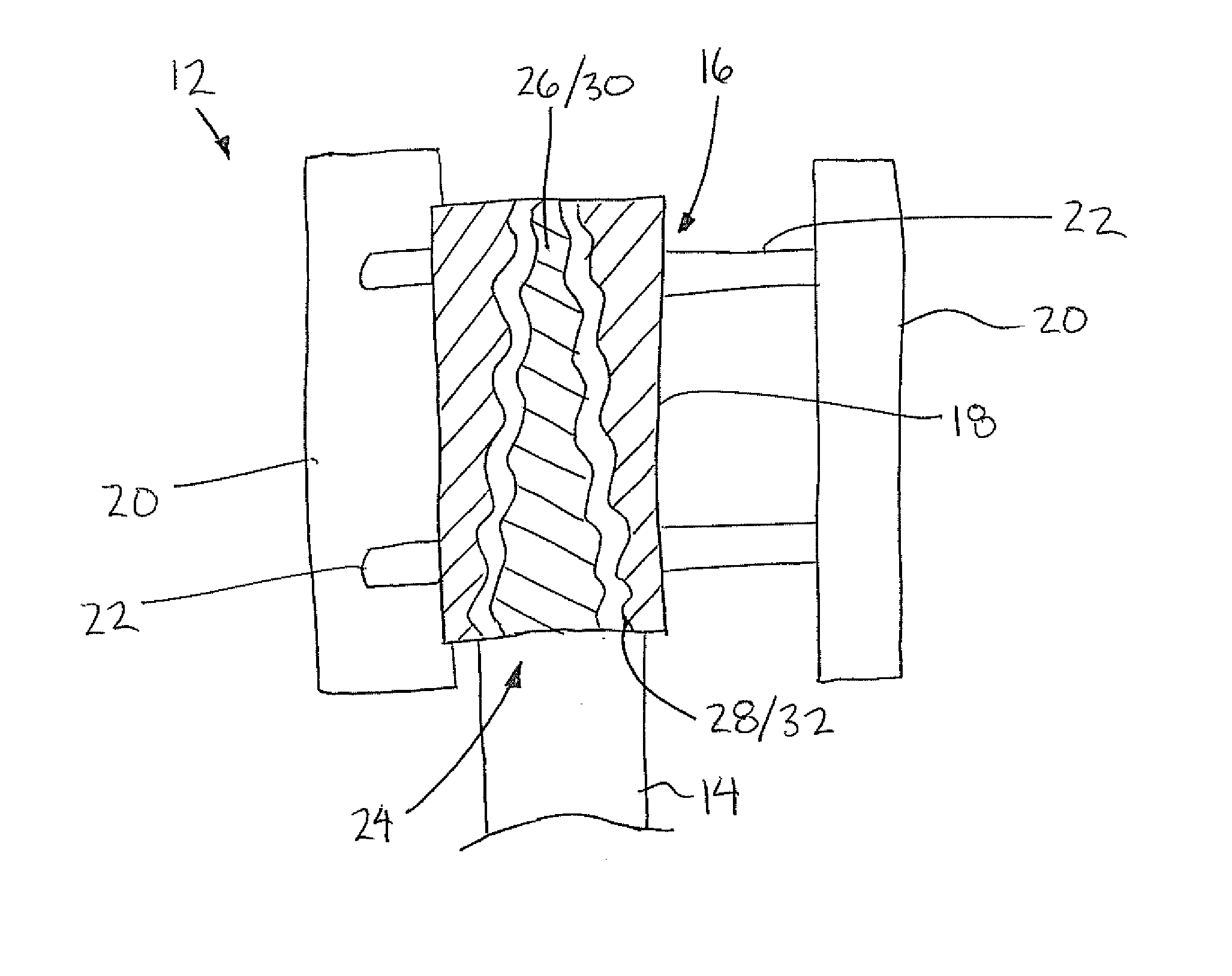
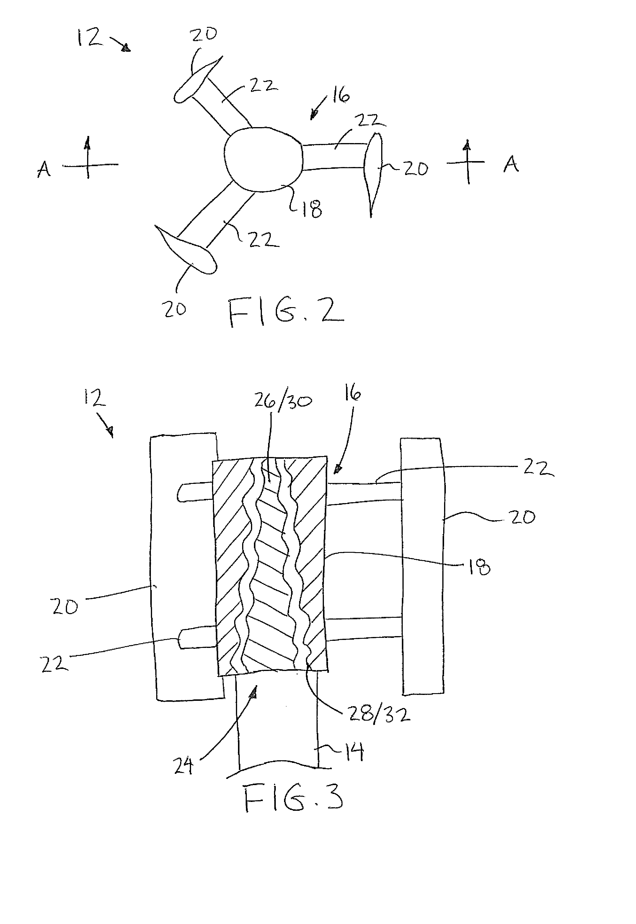
[0021]By further providing support arms for the turbine blades which are shaped to provide an axial thrust, the performance of the compressor can be improved either by reducing friction by carrying some of the weight of the compressor and turbine or by providing a more positive engagement of sealing members within the compressor.
[0039]In some embodiments use of a secondary generator in addition to a primary generator driven by compressed air permits a continuous supply of electricity sufficient for powering the control systems of the wind energy system without any additional batteries being required so as to be more environmentally friendly than known prior art configurations of wind energy storage using compressed air that require batteries for operating the electrical components in remote locations.
[0059]By providing turbine blades on a rotor which is integrally connected with the rotor of the compressor for rotation together about a common vertical axis in a vertical axis turbine as in the present invention, the efficiency losses of a drive transmission between a turbine and a compressor can be eliminated while the compressor is maintained within an optimal operating speed by the configuration of the vertical-axis turbine which is connected thereto.

Problems solved by technology

The extra mechanical transmission of rotary force of the turbine to the compressor generally results in a loss of efficiency; however the mechanical drive transfer is typically required for accommodating a different turning ratio of the compressor and the turbine components in the horizontal turbine disclosed.
Use of batteries is generally understood to be undesirable due to the negative effects thereof on the environment.

Method used


Image

  • Wind Energy Generating and Storing System
  • Wind Energy Generating and Storing System
  • Wind Energy Generating and Storing System

Examples


Embodiment Construction

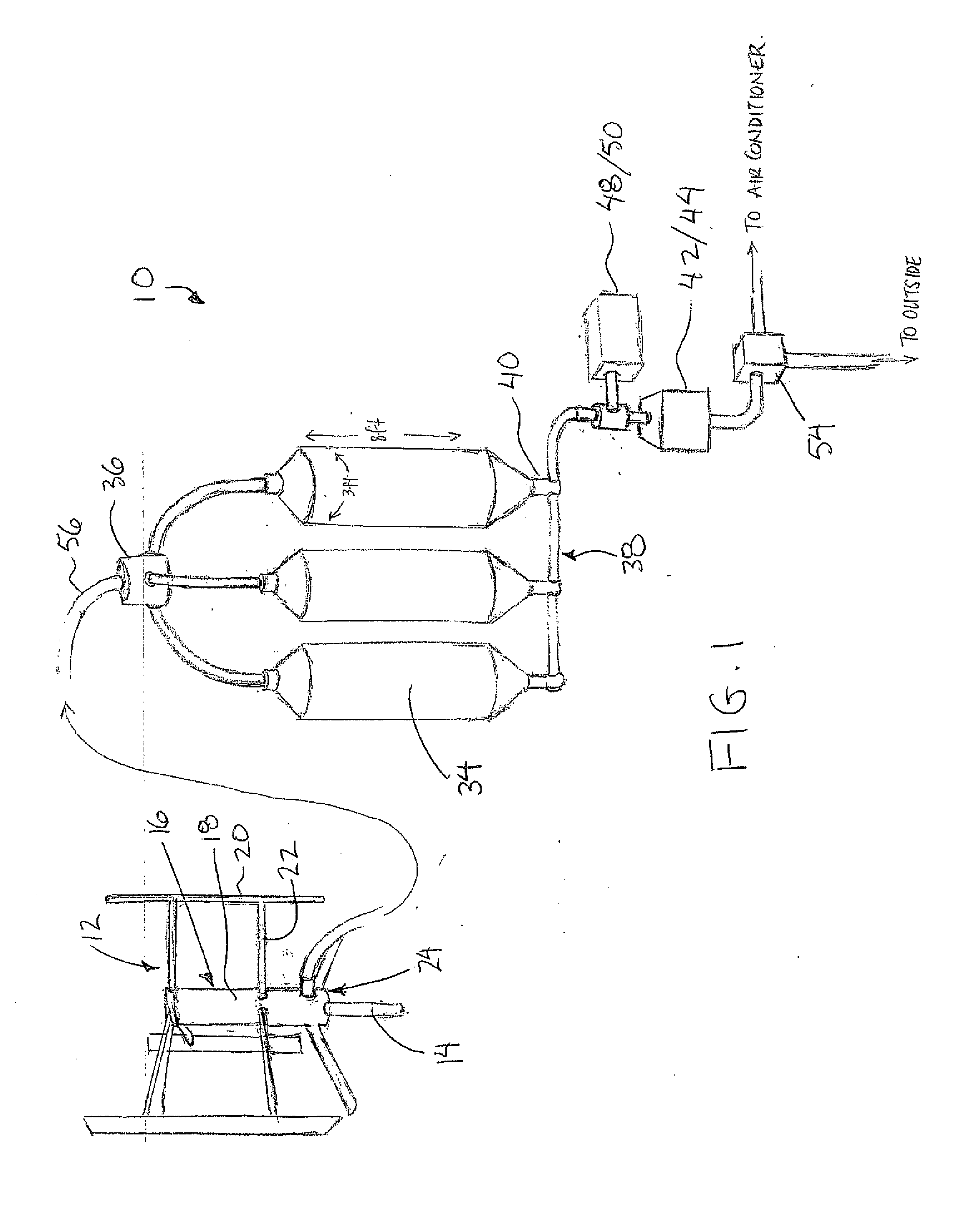
[0093]Referring to the accompanying figures there is illustrated a wind energy generating and storing system generally indicated by reference numeral 10. The system 10 is particularly suited for capturing wind energy and using the wind energy to compress air which is stored by the system for subsequent controlled release to drive suitable equipment which converts the wind energy to other useful energy forms, for example electricity and the like, on demand. Although various embodiments are described and illustrated in the following, the common features of the various embodiments will first be described herein.

[0094]The system 10 generally comprises a vertical axis lift type turbine 12 including a fixed supporting structure 14 such as a mast or tripod which supports the turbine spaced above the roof of a building for example. The turbine 12 also includes a turbine rotor 16 rotatably supported on the supporting structure 14 for rotation relative to the supporting structure about a vert...


PUM


Abstract

A wind energy system includes a vertical-axis turbine and a compressor driven by the turbine. The turbine includes blades supported on a central rotor by respective support arms having an airfoil shape so as to generate a load on the rotor in an axial direction so as to affect the performance of the compressor. The compressor rotor and the turbine rotor can be integrally coupled with one another for rotation together about a common vertical axis to minimize drive transmission losses. A primary and a secondary compressed air driven generators generate respective primary and secondary electricity from a common source of compressed air. The primary generator is controlled by an electrical controller which is powered by the secondary electricity.

Description

[0001]This application claims priority benefits from U.S. provisional application Ser. No. 61 / 173,236, filed Apr. 28, 2009.FIELD OF THE INVENTION[0002]The present invention relates to a wind energy system comprising a vertical-axis turbine which drives a compressor to compress and store air for subsequent use, for example for generating electricity.BACKGROUND[0003]The desire to make use of renewable energy is well-known and many attempts have been made to provide more efficient use of renewable energy sources so that renewable energy sources are more economical for users. Examples of prior art wind turbine systems can be found in the following patent documents: US patent publication 2006 / 0266036 by Ingersoll; US patent publication 2005 / 0016165 by Enis et al; U.S. Pat. No. 7,067,937 by Enish et al.; WO patent application 2008 / 023901 by Korea Institute of Machinery & Materials and WO patent application 2007 / 136731 by General Compression, Inc.[0004]US publication 2006 / 0266036 by Ingers...

Claims


Application Information

Patent Timeline
IPC IPC(8): F03D9/02
CPCF03D3/005F03D7/06F03D9/007F05B2220/704F05B2220/706F05B2240/40F03D13/20Y02E10/74Y02E60/15Y02E60/17F03D9/17F03D9/28F03D9/25F05B2250/25Y02E10/728Y02E60/16Y02E70/30
Inventor STUART, ALEX J.PHILLIPS, JUSTIN DAVID
Owner STUART ALEX J
Learn More