Fuel Cell System Comprising at Least One Fuel Cell

Inactive Publication Date: 2012-02-16
DAIMLER AG
View PDF5 Cites 6 Cited by
  • Summary
  • Abstract
  • Description
  • Claims
  • Application Information

AI Technical Summary

Benefits of technology

[0005]Accordingly, the present invention improves a fuel cell system in such a manner that no hydrogen emissions reach the environment, and that the fuel cell system is operated with a best possible use of the available energy.
[0007]The construction of the fuel cell system according to the invention thus permits conversion of hydrogen-containing exhaust gas from the anode region together with residual oxygen in the used air from the cathode region and thus prevents an emission of hydrogen to the environment of the fuel cell system. Additionally, the used air will be clearly hotter behind the exchanging device by means of the resulting exhaust heat, as without the catalytic material in the used air side of the exchanging device. This allows additional energy to be supplied to the turbine. The energy resulting from the conversion of the hydrogen-containing exhaust gas can thus be used beneficially in the fuel cell system, in that it supports the drive of the turbine.
[0009]This arrangement permits an additional fuel to be supplied as fuel-containing gas in addition to the exhaust gas from the anode region. This fuel could, in principle, be an arbitrary fuel. If the fuel cell system is, however, operated with hydrogen, and this hydrogen is present in any case, this hydrogen can be used as additional fuel in an ideal manner. The supply of the additional fuel to the exchanging device, and thus to the catalytic material in the used air side of the exchanging device, leads to an increased conversion of fuel with the residual oxygen in the used air. This generates additional heat, which then clearly increases the power that can be recalled via the turbine. This additional energy can then be used for the drive of the compressor.
[0013]This can, for example, take place such that the two regions are not in any or only an indirect thermal contact to each other, for example such that a material conducting heat comparatively poorly or an air gap is realized between the intake air side and the used air side of the exchanging device in this region. It can thereby avoid the exhaust heat resulting in the region of the catalytic material, and here particularly the heat resulting during the operation with additional fuel, heats the intake air to the cathode region of the fuel cell in an unnecessary manner.
[0014]The fuel cell system according to the invention in all its disclosed versions thus permits a simple, compact and thus also cost-efficient construction with an arrangement ideal for the life span and the efficiency that can be achieved. The fuel cell system according to the invention is thus particularly suitable for the use in a means of transport, and here for the generation of power for the drive and / or electrical auxiliary users in the means of transport. A means of transport in the sense of the present invention is meant to be any type of means of transport on land, on water or in the air, wherein a particular attention is certainly in the use of these fuel cell systems for motor vehicle with no rails, without the use of a fuel cell system according to the invention being restricted hereby.

Problems solved by technology

This operating guidance represents a corresponding advantage for the cold start of such a fuel cell system, for the regular operation it is, however, very critical to supply this exhaust heat to the cooling water, as the cooling surface available, for example with a use in a vehicle, is rather not or only hardly sufficient to cool the fuel cell sufficiently.
Additionally, the exhaust heat resulting in the region of the catalytic burner is not used actively with the construction of US 2005 / 0019633 A1, apart for the cold start case.

Method used


Image

  • Fuel Cell System Comprising at Least One Fuel Cell
  • Fuel Cell System Comprising at Least One Fuel Cell

Examples


Embodiment Construction

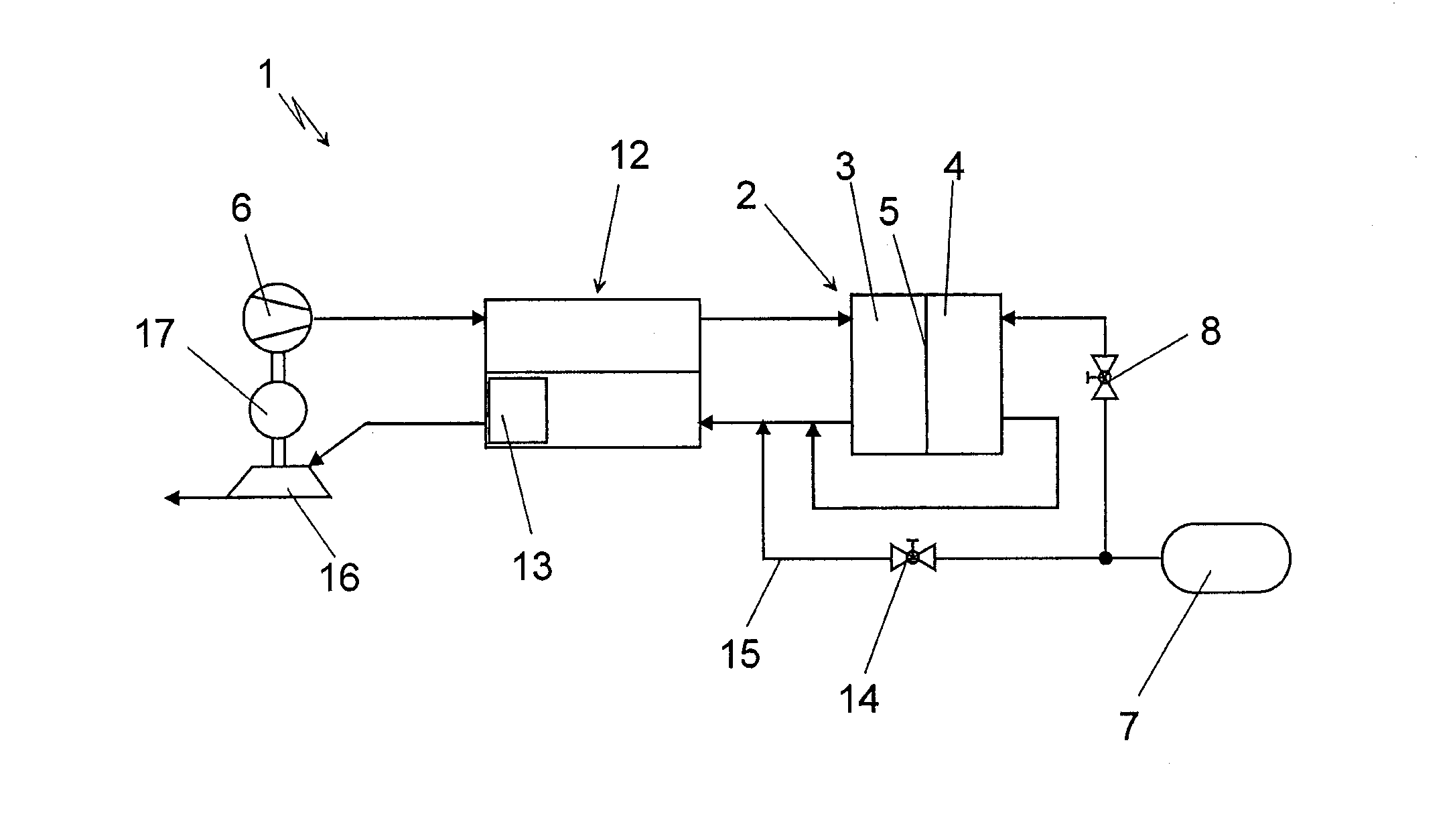
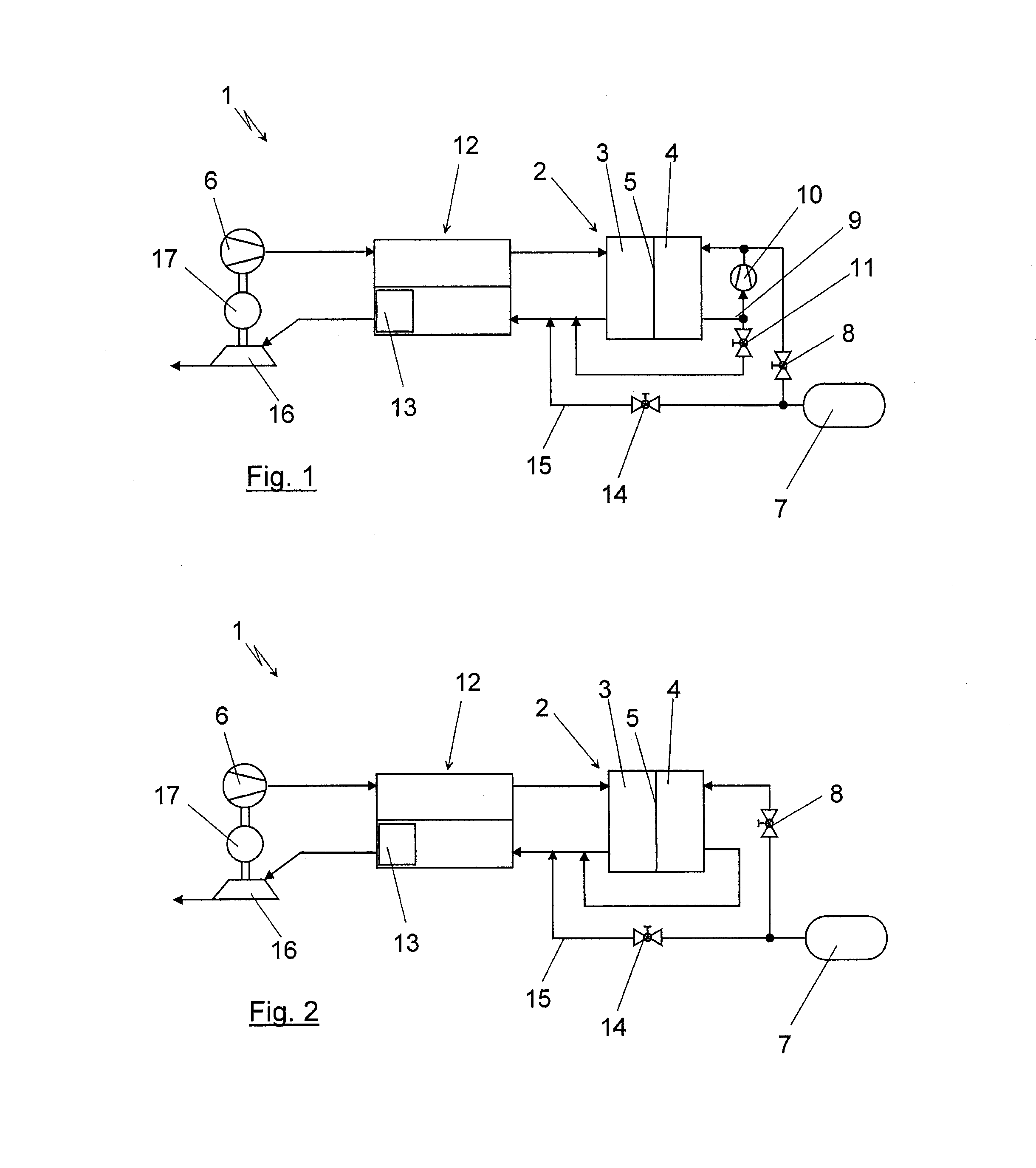
[0019]The depiction in the following figures shows only the components necessary for the understanding of the present invention in a highly schematized depiction of the very complex fuel cell system per se. It should thereby be understood for the fuel cell system that further components, as for example a cooling cycle and the like are also provided in the fuel cell system, even though these are not considered in the figures shown in the following.

[0020]FIG. 1 shows a fuel cell system 1 comprising a fuel cell 2. The fuel cell 2 includes a fuel cell 2 constructed of a stack of individual cells in a usual manner. A cathode region 3 and an anode region 4 is formed in the fuel cell 2, which regions are separated from each other by a PE membrane 5 in the exemplary embodiment shown here. In the exemplary embodiment shown in FIG. 1, an intake air flow is supplied to the cathode region 3 via a compressor 6. The compressor 6 can thereby, for example, be designed as a screw compressor or as a ...


PUM

PropertyMeasurementUnit
structureaaaaaaaaaa
electrical poweraaaaaaaaaa
energyaaaaaaaaaa

Abstract

A fuel cell system includes a fuel cell with cathode and anode regions. The fuel cell system also includes an exchanging device through which an intake air flow flows to the cathode region and a used air flow is discharged from the cathode region. In the exchanging device, heat is transferred from the intake air flow to the used air flow, and water vapor is simultaneously transferred from the used air flow to the intake air flow. A compressor is arranged downstream of the exchanging device to receive used air. A catalytic material is arranged upstream of the turbine, to which material can be supplied a fuel-containing gas. The catalytic material is integrated into the exchanging device on the used air side and an exhaust gas from the anode region is supplied to the used air side of the exchanging device.

Description

BACKGROUND AND SUMMARY OF THE INVENTION[0001]The invention relates to a fuel cell system comprising at least one fuel cell.[0002]A generic fuel cell system is described in German patent document DE 10 2007 003 144 A1. The fuel system comprises an exchange device, which combines the two functions “cooling” and humidification”. The exchanging device, which is referred to as a function unit in that document, permits a material flow from the exhaust air of the fuel cell to the intake air to the fuel cell, while a heat exchange occurs from the intake air heated by a compression device to the comparatively cool exhaust air. The construction of DE 10 2007 003 144 A1 additionally shows a construction, where the air supply of the fuel cell system is realized via a compressor, which can be driven by a turbine and / or an electric motor. This generally known construction with fuel cell systems is also called an electric turbocharger and permits the at least supporting drive of the compressor, an...

Claims


Application Information

Patent Timeline
Patent Type & Authority Applications(United States)
IPC IPC(8): H01M8/06
CPCH01M8/04097H01M8/04111Y02E60/50H01M8/0662H01M8/04141
Inventor KONRAD, GERHARDSTERK, FELIX
Owner DAIMLER AG
Why Eureka
Try Eureka