Gas sensor control apparatus controlling output characteristic of gas sensor

a technology of gas sensor and control apparatus, which is applied in the direction of measurement devices, instruments, scientific instruments, etc., can solve the problems of affecting the reaction of lean components, affecting the response time of gas sensors, and affecting the level of output of gas sensors, so as to reduce the emitted amount of lean components, shorten the response time of gas sensors, and reduce the effect of lean components

Active Publication Date: 2012-02-23
DENSO CORP
View PDF2 Cites 41 Cited by
  • Summary
  • Abstract
  • Description
  • Claims
  • Application Information

AI Technical Summary

Benefits of technology

[0029]When the internal combustion engine is running in a transient period of time in which a load on the internal combustion engine is increasing or in a high load steady state period of time in which the load on the internal combustion engine stops increasing, so that the internal combustion engine is in a high load condition, the controller determines that the change request is made to shorten the response time of the gas sensor upon a change in the air-fuel ratio from rich to lean and changes a degree of the response time of the gas sensor in the transient period of time to be shorter than that in the high load steady state period of time.
[0030]Specifically, the period of time in which the engine is running in the high load condition includes the transient period of time in which the load on the engine is increasing and the high load steady state period of time in which the load on the engine stops increasing, and the engine is kept running in the high load condition. In either of the transient period of time or the high load steady state period of time, the quantity of fresh air inducted into the engine usually becomes great, so that the lean components such as the NOx components increase. It is, therefore, advisable that the response time of the gas sensor upon a change in air-fuel ratio to the lean state be shortened in order to decrease an emitted amount of the lean components. However, there is fear that the emitted amount of the lean components increase greatly in the transient period of time as compared with the high load steady state period of time. The controller, thus, changes the response time of the gas sensor upon a change in the air-fuel ratio from rich to lean in the transient period of time to be shorter than that in the high load steady state period of time. This ensures a balance in emitting the lean components between the transient period of time and the high load steady state period of time.

Problems solved by technology

The production of the electromotive force O2 sensor of the above publication requires modifying the structure of a typical O2 sensor greatly, thus resulting in an increase in production cost thereof.
When the gas component has changed in concentration or composition thereof, some components contained in the gas immediately before such changing may remain residing around the gas sensor, which results in a delay in change in level of the output of the gas sensor in response to the change in concentration or composition of the gas component ((i.e., a lag of response time of the gas sensor).
When the air-fuel ratio changes from the rich to lean state, rich components of the exhaust gas such as HC components stay around the gas sensor, which will disturb the reaction of lean components such as NOx components on the electrodes of the gas sensor.
This results in a decrease in responsivity of the gas sensor to the change in the air-fuel ratio to the lean side.
However, there is fear that the emitted amount of the lean components increase greatly in the transient period of time as compared with the high load steady state period of time.

Method used


Image

  • Gas sensor control apparatus controlling output characteristic of gas sensor
  • Gas sensor control apparatus controlling output characteristic of gas sensor
  • Gas sensor control apparatus controlling output characteristic of gas sensor

Examples


first embodiment

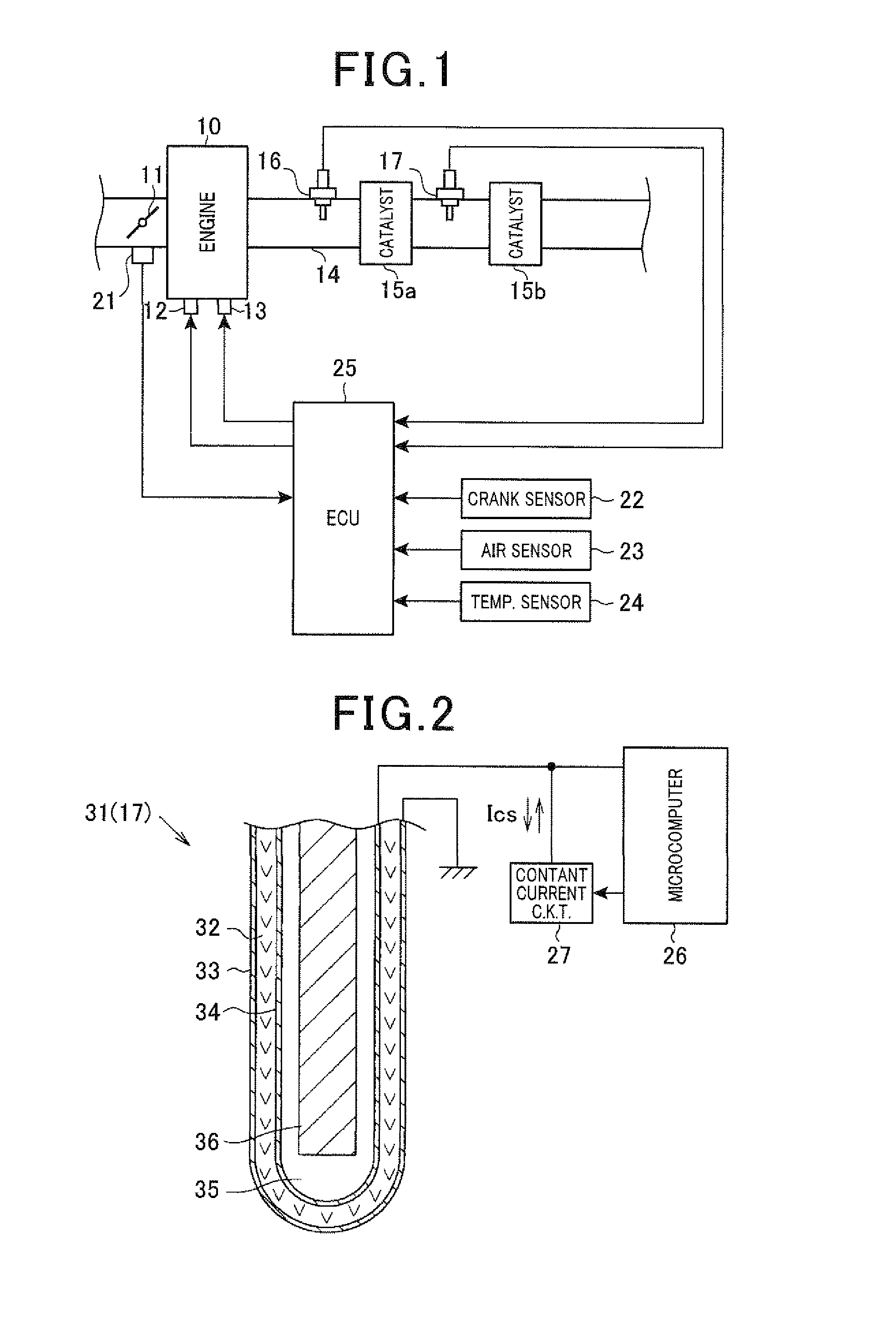
[0057]Referring to the drawings, wherein like reference numbers refer to like parts in several views, particularly to FIG. 1, there is shown an engine control system which is designed to monitor outputs of gas sensors installed in an exhaust pipe of an internal combustion engine mounted in an automotive vehicle to perform some engine control tasks. The engine control system is equipped with a gas sensor control apparatus and includes an electronic control unit (ECU) 25 to control the quantity of fuel to be sprayed into an internal combustion engine 10 (e.g., an air-fuel ratio of a mixture to be supplied to the engine 10), the ignition timing of the fuel, etc.

[0058]The engine 10 is a gasoline engine and equipped with an electronically-controlled throttle valve 11, fuel injectors 12 (only one is shown for the brevity of illustration), and an ignition device (i.e., an igniter) 13. The exhaust pipe 14 extending from the engine 10 has installed therein catalytic converters 15a and 15b w...

second embodiment

[0106]The engine control system of the second embodiment will be described below which is designed to apply the constant current Ics to the O2 sensor 17 based on values of the air-fuel ratio of the exhaust gas before and after the air-fuel ratio changes between the rich and lean state to change the response speed of the O2 sensor 17. Specifically, when the air-fuel ratio has changed, the microcomputer 26 switches the constant current Ics between the negative constant current −Ics and the positive constant current +Ics. This is effective, especially in the case where the cycle at which the air-fuel ratio changes is relatively long.

[0107]FIG. 10 is a flowchart of a response control program to be executed by the microcomputer 26 cyclically at a regular interval to change the response speed of the O2 sensor 17.

[0108]After entering the program, the routine proceeds to step S21 wherein the output of the O2 sensor 17 is sampled. The routine proceeds to step S22 wherein it is determined whe...


PUM

PropertyMeasurementUnit
temperatureaaaaaaaaaa
electromotive forceaaaaaaaaaa

Abstract

A gas sensor control apparatus is provided which controls an operation of a gas sensor made up of a solid electrolyte body and a pair of electrodes to output a signal indicating the concentration of a given gas component contained in gas. The gas sensor control apparatus includes a constant current circuit that is connected electrically to one of the electrodes of the gas sensor and supplies a constant current thereto and a controller. The controller supplies a constant current to the gas sensor so that it flows from one of the electrodes to the other in a selected direction, thereby changing a response time the gas sensor takes to react to a change in concentration of the gas component. This results in an increased accuracy, for example, in controlling an air-fuel ratio of a mixture to an internal combustion engine in an engine control system.

Description

CROSS REFERENCE TO RELATED DOCUMENT[0001]The present application claims the benefits of priority of Japanese Patent Application No. 2010-184372 filed on Aug. 19, 2010 and Japanese Patent Application No. 2011-117453 filed May 25, 2011, disclosures of which are incorporated herein by reference.BACKGROUND[0002]1. Technical Field[0003]The present application relates generally to a gas sensor control apparatus designed to change an output characteristic such as a response time of a gas sensor as needed.[0004]2. Background Art[0005]Gas sensors are known which measure the concentration of oxygen contained in exhaust gas from an automotive engine as representing an air-fuel ratio of a mixture supplied to the engine. For example, typical electromotive force O2 sensors work to output an electric signal which is different in level between when the exhaust gas is rich in fuel and when the exhaust gas is lean in fuel. Specifically, such a type of O2 sensors produces about 0.9V when an air-fuel r...

Claims


Application Information

Patent Timeline
Patent Type & Authority Applications(United States)
IPC IPC(8): G01N27/409G01N27/407
CPCG01N27/409G01N27/407
Inventor MATSUOKA, MIKIYASUKAWAKATSU, YASUHIRONAKATA, SHINGOMISHIMA, TAKAO
Owner DENSO CORP
Why Eureka
Try Eureka