Semiconductor device, manufacturing method thereof, and manufacturing method of semiconductor module
a semiconductor module and semiconductor technology, applied in the direction of printed circuit aspects, sustainable manufacturing/processing, final product manufacturing, etc., to achieve the effect of improving the yield of mounting the semiconductor device and improving the reliability of the semiconductor devi
- Summary
- Abstract
- Description
- Claims
- Application Information
AI Technical Summary
Benefits of technology
Problems solved by technology
Method used
Image
Examples
embodiment 1
[0092]A semiconductor device of the present embodiment will be described with reference to the drawings.
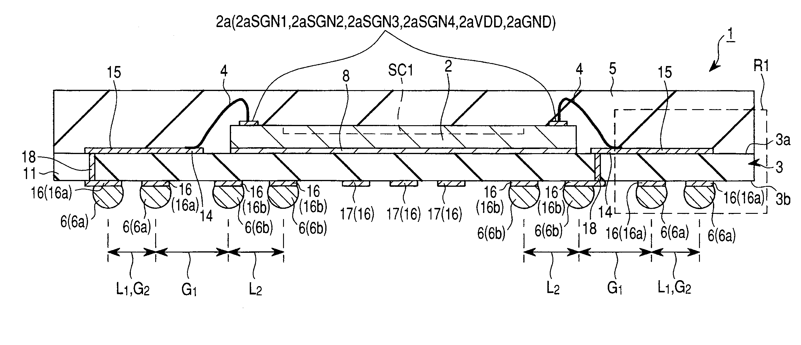
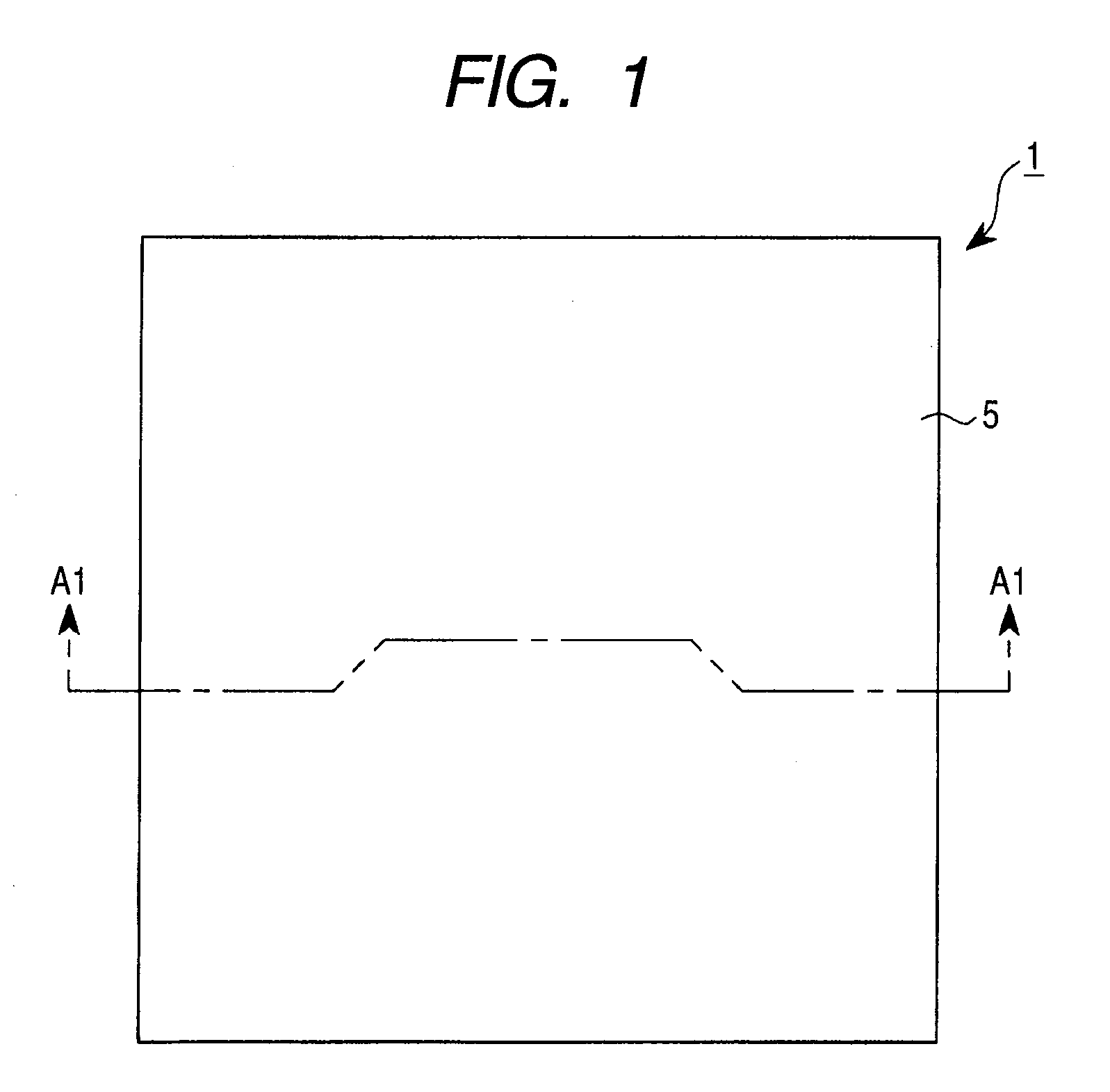
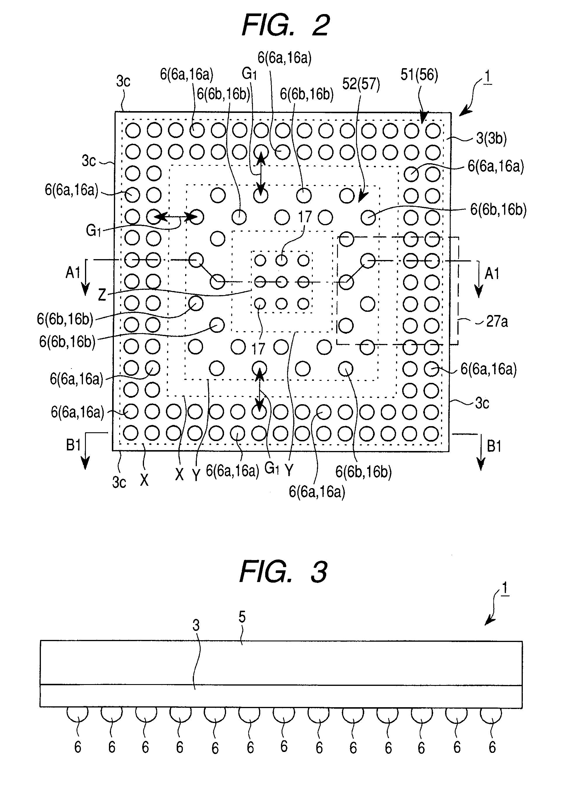
[0093]FIG. 1 is a top view (plan view) of a semiconductor device 1 as an embodiment of the present invention. FIG. 2 is a bottom view (bottom surface view, back surface view, or plan view) of the semiconductor device 1. FIG. 3 is a side view of the semiconductor device 1. FIG. 4 is a cross-sectional view (side cross-sectional view) of the semiconductor device 1. A cross section along the line A1-A1 of each of FIGS. 1 and 2 substantially corresponds to FIG. 4. FIG. 5 is a conceptual plan view (top view) of a semiconductor chip 2 used in the semiconductor device 1. FIG. 6 is a circuit block diagram showing a coupling relationship between the semiconductor chip 2 and external LSIs. FIG. 7 is a conceptual plan perspective view (top view) of the semiconductor device 1 when the semiconductor device 1 is viewed through a mold resin 5.
[0094]The semiconductor device 1 of the present embodi...
embodiment 2
[0215]A semiconductor device of Embodiment 2 of the present invention will be described with reference to the drawings.
[0216]FIG. 43 is a cross-sectional view (side cross-sectional view) of the semiconductor device 1 according to Embodiment 2, which corresponds to FIG. 4 described above.
[0217]In the semiconductor device 1 of FIGS. 1 to 4 described above, the plural terminals for testing 17 are arranged in the vicinity of the center of the lower surface 3b of the wiring substrate 3. However, the present embodiment and Embodiments 3 to 8 shown below are not limited thereto.
[0218]For example, in a case where the number of the solder balls 6 serving as signal supply paths further increases as a semiconductor device becomes higher in functionality, and all the solder balls 6a and 6b in the first solder ball group 51, and in the second solder ball group 52 are used exclusively as the solder balls 6 serving as the signal supply paths, solder balls 6f (or lands 16f for coupling to the solde...
embodiment 3
[0221]A semiconductor device of Embodiment 3 of the present invention will be described with reference to the drawings.
[0222]FIG. 44 is a bottom view (bottom surface view, back surface view, or plan view) of a semiconductor device 1a of the present embodiment, which corresponds to FIG. 2 of Embodiment 1 described above. FIGS. 45 to 48 are illustrative views of the semiconductor device 1a, in which FIG. 45 shows only the solder balls 6 (i.e., solder balls 6c) belonging to a solder ball group 51a at the lower surface 3b of the wiring substrate 3 of the semiconductor device 1a, and corresponds to a plan view in which the depiction of the solder balls 6 belonging to solder ball groups 51a and 52a is omitted. FIG. 46 shows only the solder balls 6 (i.e., solder balls 6d) belonging to the solder ball group 51b at the lower surface 3b of the wiring substrate 3 of the semiconductor device 1a, and corresponds to a plan view in which the depiction of the solder balls 6 belonging to the solder ...
PUM
 Abstract
Description
Claims
Application Information
 - R&D
- Intellectual Property
- Life Sciences
- Materials
- Tech Scout
- Unparalleled Data Quality
- Higher Quality Content
- 60% Fewer Hallucinations
Browse by: Latest US Patents, China's latest patents, Technical Efficacy Thesaurus, Application Domain, Technology Topic, Popular Technical Reports.
© 2025 PatSnap. All rights reserved.Legal|Privacy policy|Modern Slavery Act Transparency Statement|Sitemap|About US| Contact US: help@patsnap.com


