Cooling Methodology for High Brightness Light Emitting Diodes

a technology of light-emitting diodes and cooling methods, which is applied in the direction of electrical apparatus contruction details, light-emitting and heating apparatuses, semiconductor devices for light sources, etc., can solve the problems of substantial surface turbulence and substantially greater cooling, and achieve the effect of large size, cost and efficiency benefits

Inactive Publication Date: 2012-02-23
COOLIANCE
View PDF6 Cites 35 Cited by
  • Summary
  • Abstract
  • Description
  • Claims
  • Application Information

AI Technical Summary

Benefits of technology

[0008]The present invention will allow an end user to create a modified plenum chamber in which fan-driven air is drawn into a housing and channeled through a pinned or finned heat sink structure which presents a large surface area to contact turbulent moving air. Heat from a heat source is transferred to the heat sink structure for ultimate transfer to the surrounding air. In other words, the present invention must use as much of the volumetric space in the light-fixture-housing internal as possible for thermal management purposes unencumbered by co-located power supply circuits. Such circuits can be more readily optimized for size, cost, and electrical safety agency considerations if fabricated as external modules, as is current industry practice for most light fixtures employing HID lamps (which typically use external ballasts) or low voltage halogen lamps (which typically use external magnetic or electronic transformers).
[0009]The design of the heat sink structure, coupled with significantly reduced air speed, serves to reduce back-pressure-related compromising of cooling objectives and allows more useful air to flow across all surface areas of the heat sink structure. In reference to the article “Fan speed vs. Operating Life and Acoustic noise”, a very significant reduction in fan speed reduces not only the back pressure issues but also greatly reduces acoustic noise, minimizes dust susceptibility over long periods of time, and significantly increases fan life (2).
[0010]It is a premise of the invention that the arrangement can provide numerous cooling benefits compared to conventional methods (i.e. natural convection, including versions using what is called “the chimney effect”) and at much lower acoustic noise levels than generally thought feasible with traditional techniques using combinations of heat sinks and fans. Moreover, the approach can achieve much greater ratios of no-air-flow to high-speed-air-flow thermal resistance than is suggested as being possible by technical literature on commercial heat sink structures.

Problems solved by technology

With such a plate, even slow moving air, impacting the plate perpendicularly creates substantial surface turbulence and substantially greater cooling then if air were moving in a way parallel to the plane of the plate.

Method used


Image

  • Cooling Methodology for High Brightness Light Emitting Diodes
  • Cooling Methodology for High Brightness Light Emitting Diodes
  • Cooling Methodology for High Brightness Light Emitting Diodes

Examples


Embodiment Construction

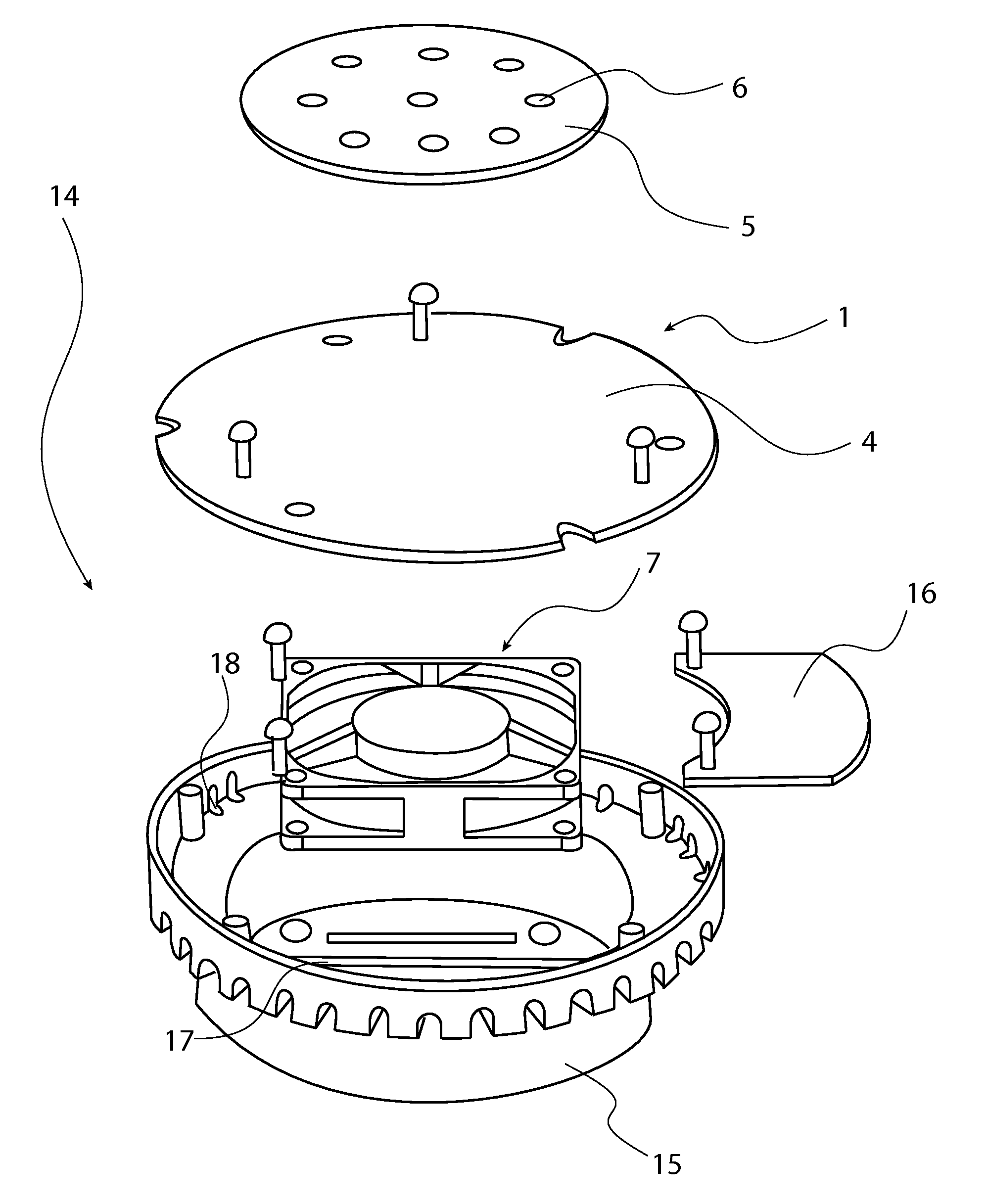
[0038]All illustrations of the drawings are for the purpose of describing selected versions of the present invention and are not intended to limit the scope of the present invention as a cooling apparatus for high brightness LEDs. Referring to FIG. 15, the present invention comprises mainly of a cooling enclosure 14, a 1, a cooling fan 7, a LED substrate 5, and a plurality of LEDs 6.

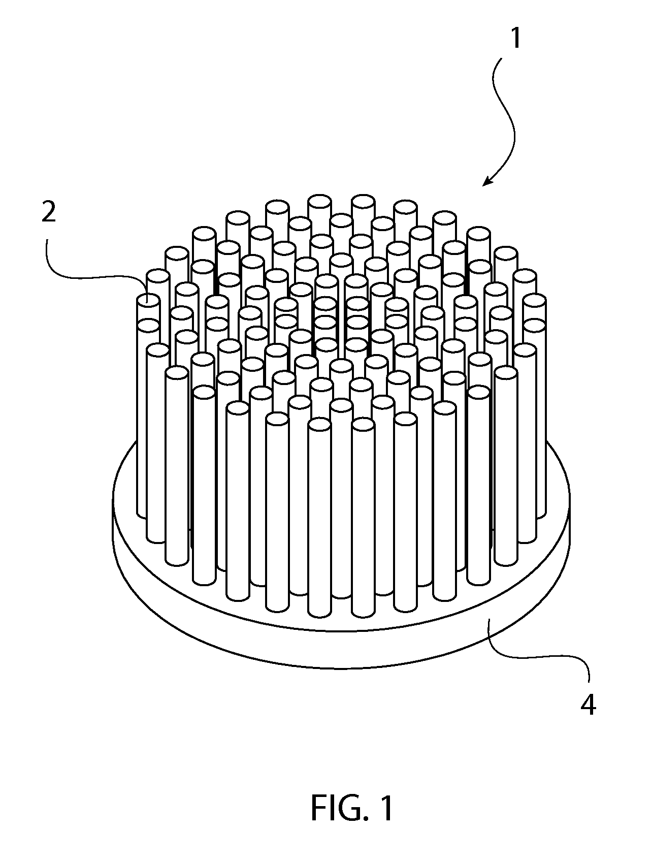
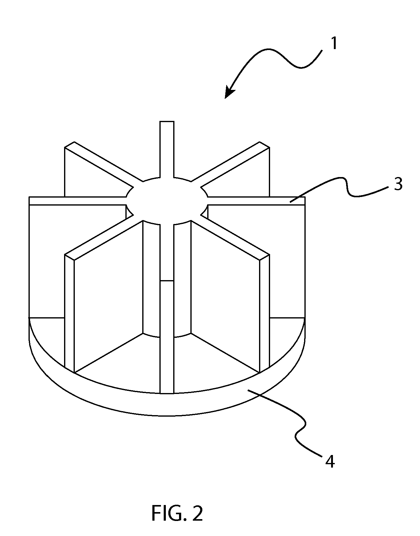
[0039]Referring to FIG. 1, FIG. 2, FIG. 14, the heat sink 1 can be fabricated by forging or die casting. The heat sink 1 consists of a mounting surface 4 from which there are a plurality of protrusions 2, 3 from its surface. One type of protrusion is a pin protrusion 2, which is a thin solid cylinder with a structure effective for heat transfer. In other designs, the protrusions could take the form of a plurality of fin protrusions 3. In certain instances, fin protrusions 3 can result in more total protrusion surface area, reduced air flow resistance, or both, thereby resulting in more cooling effectiven...


PUM


Abstract

The present invention is a compact, highly efficient method for convectively cooling substrates, where the substrates contain light emitting diodes (LEDs) or other highly dissipative electronic components. The methodology exhibits very low acoustic noise, extended operating life of moving parts and minimum susceptibility to dust. Also, the improved cooling methodology for high brightness light emitting diodes employs one or more high-density, high-surface-area, single or multiple-element metallic structures having superior heat-transfer properties in the presence of low-speed, minimally turbulent air flow, and enhanced electronic-power-management.

Description

[0001]The current application claims a priority to the U.S. Provisional Patent application Ser. No. 61 / 376,165 filed on Aug. 23, 2010.FIELD OF THE INVENTION[0002]The present invention relates generally to cooling apparatuses for high brightness light emitting diodes (LEDs). More specifically, it details the use of heat sinks and fans to cool down LEDs in lighting fixtures and circulate air throughout the fixture so that they operate at maximum efficiency.BACKGROUND OF THE INVENTION[0003]In many general-illumination light emitting diode lighting applications, such as those for fully visible or ceiling-recessed cylindrical-can fixtures used in retail, architecture or entertainment applications, there is a need to remove substantial heat generated by the high brightness LEDs. In such applications, the light output of a given form factor can be limited, not primarily by the electronic drivers or even the LEDs themselves, but rather by managing the amount of LED-originated heat which can...

Claims


Application Information

Patent Timeline
Patent Type & Authority Applications(United States)
IPC IPC(8): H05K7/20H05B44/00
CPCF21V23/003F21V23/02F21V29/027F21Y2101/02H05B33/0803F21V29/83F21V29/65F21V29/677F21V29/74F21V29/80F21V29/507F21Y2115/10H05B45/395H05B45/375Y02B20/30
Inventor RODRIGUEZ, EDWARD T.
Owner COOLIANCE
Why Eureka
Try Eureka