Composite structure

a composite and structure technology, applied in the field of composite structures, can solve the problems of complex and time-consuming operation of delamination between, inability to increase the thickness abruptly, and inability to achieve the effect of increasing the pull-through strength of the join

Inactive Publication Date: 2012-02-23
AIRBUS OPERATIONS LTD
View PDF5 Cites 21 Cited by
  • Summary
  • Abstract
  • Description
  • Claims
  • Application Information

AI Technical Summary

Benefits of technology

[0023]The prongs may have a simple triangular profile, or at least one of the prongs may have a transverse cross-sectional area which increases from the tip of the prong to form a pointed head, and then decreases to form an undercut face. The prongs may push aside fibres in the composite material as they pierce the composite part, and then the fibres spring back behind the undercut face. The undercut face can thus increase the pull-through strength of the joint. Alternatively the prongs may cut the fibres as they pierce the composite part.

Problems solved by technology

The hole creates weakness in the structure which requires the thickness of each part to be increased locally in the region of the hole.
It is not possible to increase the thickness abruptly, since this will tend to cause de-lamination between the plies of material within each part.
Forming the ramps 3, 4 in the composite parts is a complex and time consuming operation, particularly for a large component such as an aircraft wing cover or spar where a large number of such joints must be formed.
Also the ramps 3, 4 add undesirable weight to the joint.
The structure of FIG. 2 suffers from similar problems to the joint of FIG. 1: that is, forming the ramps 8, 9 in the composite spar is a complex and time consuming operation, particularly for a large aircraft.

Method used


Image

  • Composite structure
  • Composite structure
  • Composite structure

Examples


Embodiment Construction

)

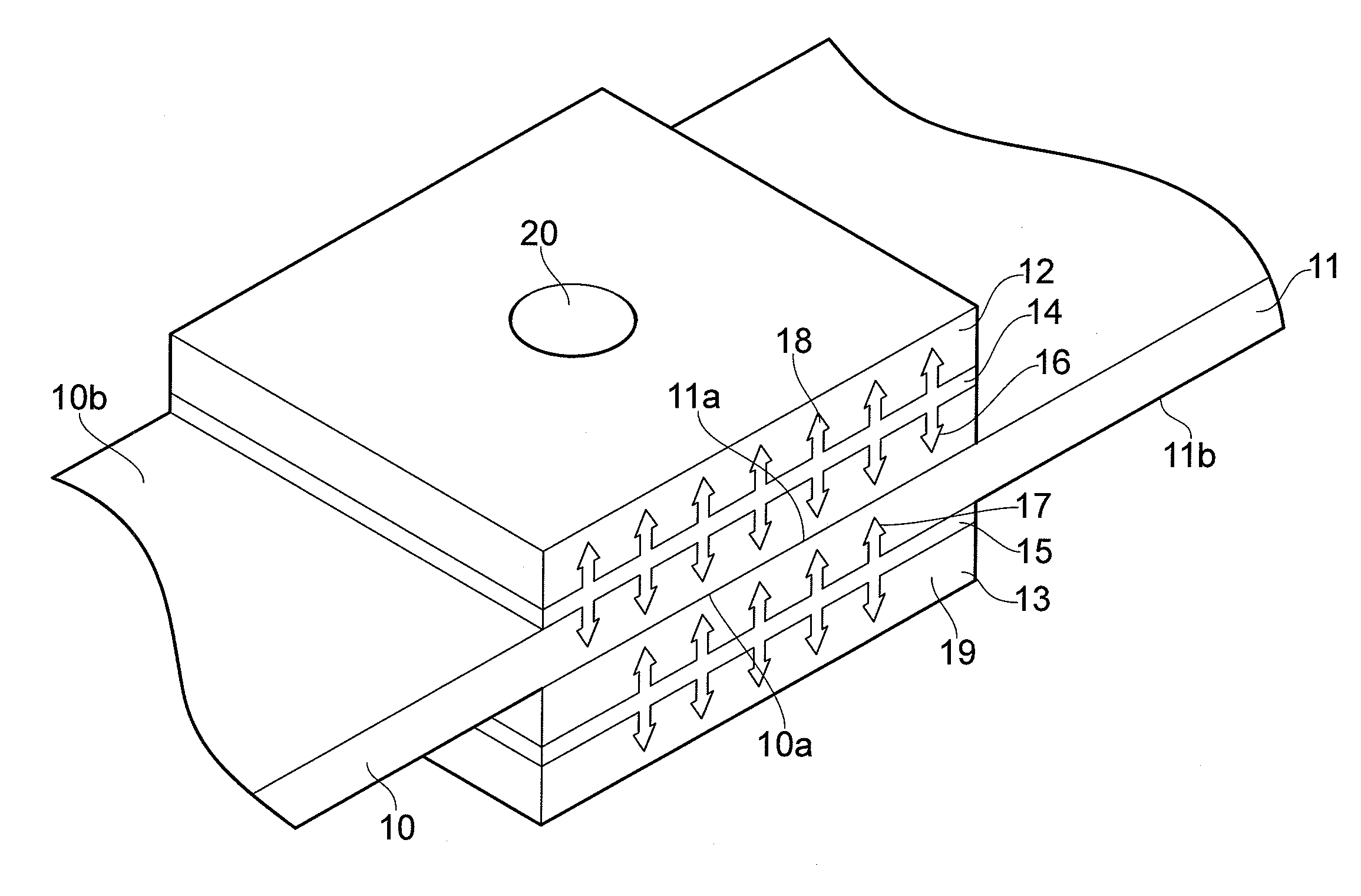
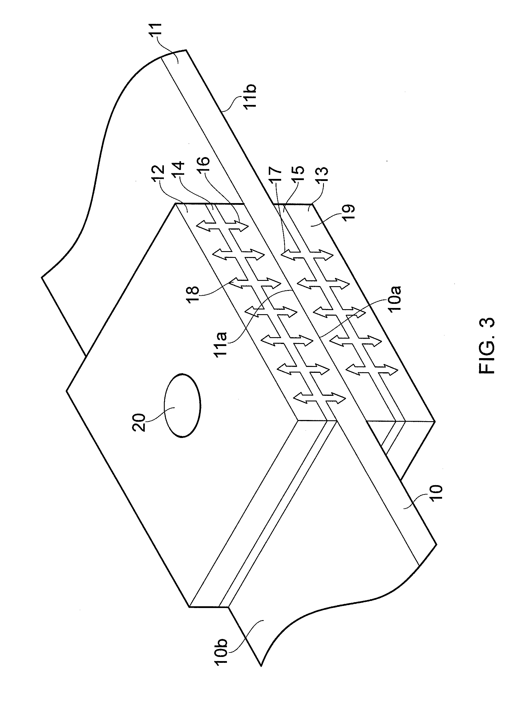
[0040]A joint shown in FIG. 3 comprises a first part 10 and a second part 11 each having an inner face 10a, 11a, and an outer face 10b, 11b. Each part is formed from a series of plies of fibre-reinforced composite material. The inner faces 10a, 11a overlap partially to form a single-lap joint. A doubler plate 12, 13 is attached to the outer face of each part by a respective interface plate 14, 15. Each interface plate carries an array of pointed prongs 16, 17 on its inner side which partially penetrates a respective one of the parts 10, 11. Each interface plate also carries an array of pointed prongs 18, 19 on its outer side which partially penetrates a respective one of the doubler plates 12, 13. A hole 20 is drilled through the joint and a fastener (not shown) is passed through the hole 20 to secure the joint.

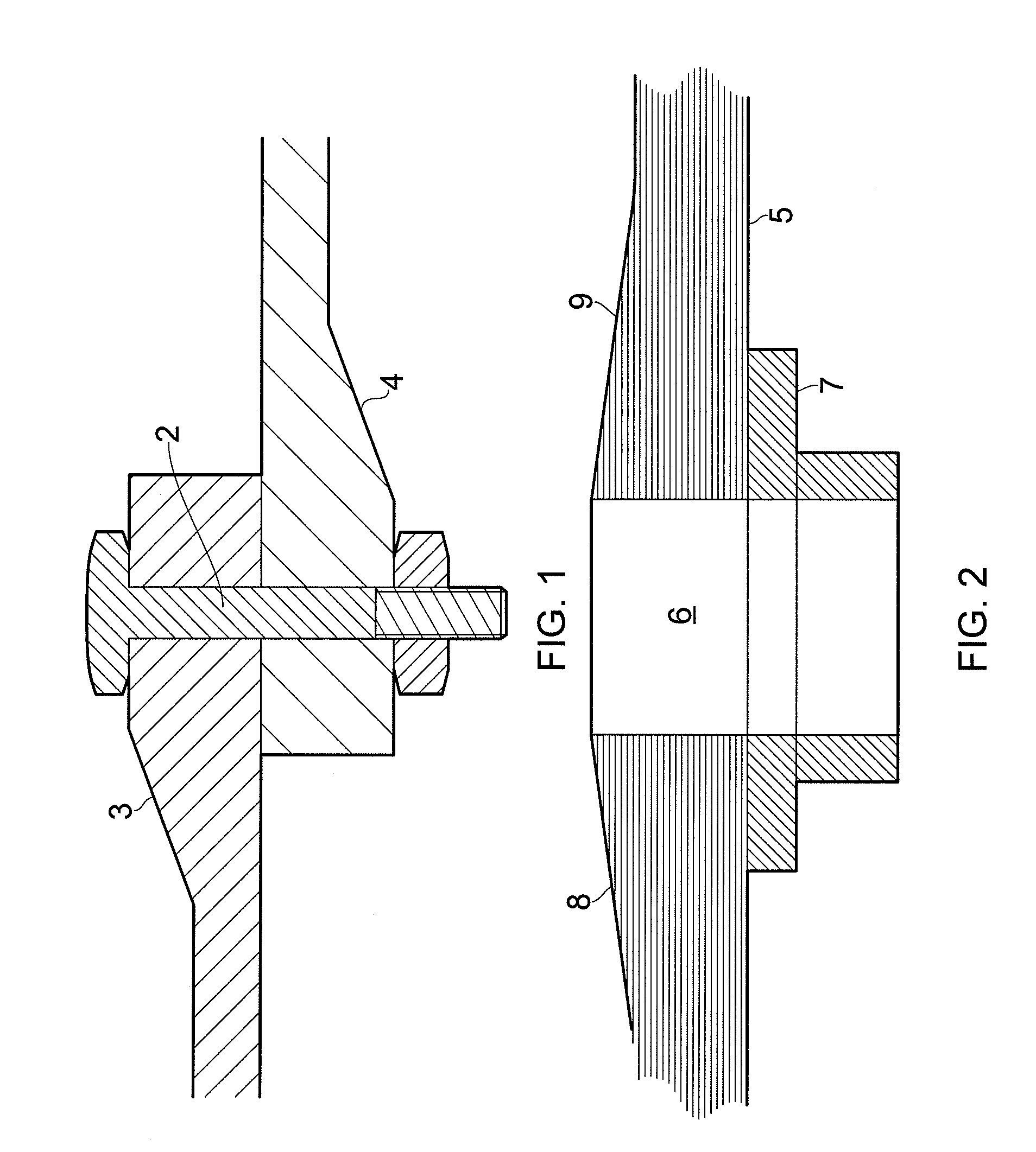
[0041]A method of manufacturing a joint similar to the joint of FIG. 3 will now be described with reference to FIGS. 4-8

[0042]An interface plate 21 is first manufactured by ...


PUM

PropertyMeasurementUnit
distanceaaaaaaaaaa
structureaaaaaaaaaa
cross-sectional areaaaaaaaaaaa

Abstract

A structure comprising a cured composite part formed from a series of plies of fibre-reinforced composite material; a doubler plate attached to the composite part by an array of pointed prongs which partially penetrate the composite part; and a hole passing through the doubler plate and the composite part. An interface plate carries the array of prongs on a first side and is attached to the doubler plate on a second side.

Description

FIELD OF THE INVENTION[0001]The present invention relates to structure with a part formed from a series of plies of fibre-reinforced composite material, and a method of manufacturing such a structure.BACKGROUND OF THE INVENTION[0002]A conventional single-lap joint for joining two fibre-reinforced composite parts is shown in FIG. 1. Each part is formed from a series of plies of fibre-reinforced composite material. A hole is drilled through the parts which are then fastened together using a pin 2 (which may be a bolt or rivet). The hole creates weakness in the structure which requires the thickness of each part to be increased locally in the region of the hole. It is not possible to increase the thickness abruptly, since this will tend to cause de-lamination between the plies of material within each part. Therefore the thickness is increased gradually by forming a ramp 3, 4 in each part with an angle of approximately three degrees.[0003]Forming the ramps 3, 4 in the composite parts is...

Claims


Application Information

Patent Timeline
Patent Type & Authority Applications(United States)
IPC IPC(8): B32B7/08B32B37/14B32B38/04
CPCB32B7/08Y10T156/1057B29L2031/3076B29C65/562B29C65/564B29C66/1122B29C66/30341B29C66/43B29C66/5346B29C66/53465B29C66/721B29C66/73941B29C66/72141B29L2031/3085Y10T428/24322Y02T50/433B29C66/7212B29C66/7392B29C66/71B29C66/7394B32B5/022B32B5/024B32B5/026B32B5/14B32B5/22B32B5/26B32B3/26B32B3/30B32B2260/023B32B2260/046B32B2262/106B32B2307/50B32B2307/718B32B2605/18B29C66/73112B29L2031/7172Y02T50/40B29K2307/04B29K2071/00B29K2063/00
Inventor SANDERSON, TIMOTHY
Owner AIRBUS OPERATIONS LTD
Why Eureka
Try Eureka