Dual-contrast mr imaging using fluid-attenuation inversion recovery (FLAIR)

a fluid attenuation recovery and dual-contrast technology, applied in the field of magnetic resonance imaging, can solve the problems of ir rf pulses that may exhibit problematic in-flow artifacts produced by csf motion, work well at a main field strength of up to 3 tesla, and achieve significant longitudinal relaxation time of brain tissue, reduce longitudinal relaxation time differences, and improve the effect of contras

Inactive Publication Date: 2012-02-23
KONINKLIJKE PHILIPS ELECTRONICS NV
View PDF2 Cites 7 Cited by
  • Summary
  • Abstract
  • Description
  • Claims
  • Application Information

AI Technical Summary

Benefits of technology

[0018]Moreover, the substances may also have different transverse relaxation times. In this case the duration of the first imaging sequence can be selected such the transverse magnetization of at least one of the substances (e.g. brain tissue) is essentially zero at the end of the first imaging sequence while the transverse magnetization of at least one other substance (e.g. CSF) is different from zero. The remaining transverse magnetization of CSF can be converted into longitudinal magnetization at the end of the first imaging sequence by means of a driven equilibrium (DRIVE) pulse, i.e. immediately before the IR RF pulse is irradiated. The short T2 components (e.g. brain tissue) will not contribute to the longitudinal magnetization after the DRIVE pulse. In this embodiment, the first imaging sequence of the invention has the effect of a magnetization preparation sequence that saturates short T2 components. In contrast to conventional FLAIR, the recovery of longitudinal magnetization of short T2 substances (e.g. brain tissue)

Problems solved by technology

It has been found particularly useful in brain and spinal imaging where brain tissue (grey and white matter) or spinal tissue is of interest and MR signals from surrounding cerebral spinal fluid (CSF) is undesirable.
FLAIR sequences that apply spatially selective IR RF pulses may exhibit problematic in-flow artifacts produced by CSF motion.
In multi slice FLAIR, however, image contrast is often not as consistent through the image slices depending on the exact delay between the IR pulse an

Method used


Image

  • Dual-contrast mr imaging using fluid-attenuation inversion recovery (FLAIR)
  • Dual-contrast mr imaging using fluid-attenuation inversion recovery (FLAIR)
  • Dual-contrast mr imaging using fluid-attenuation inversion recovery (FLAIR)

Examples


Embodiment Construction

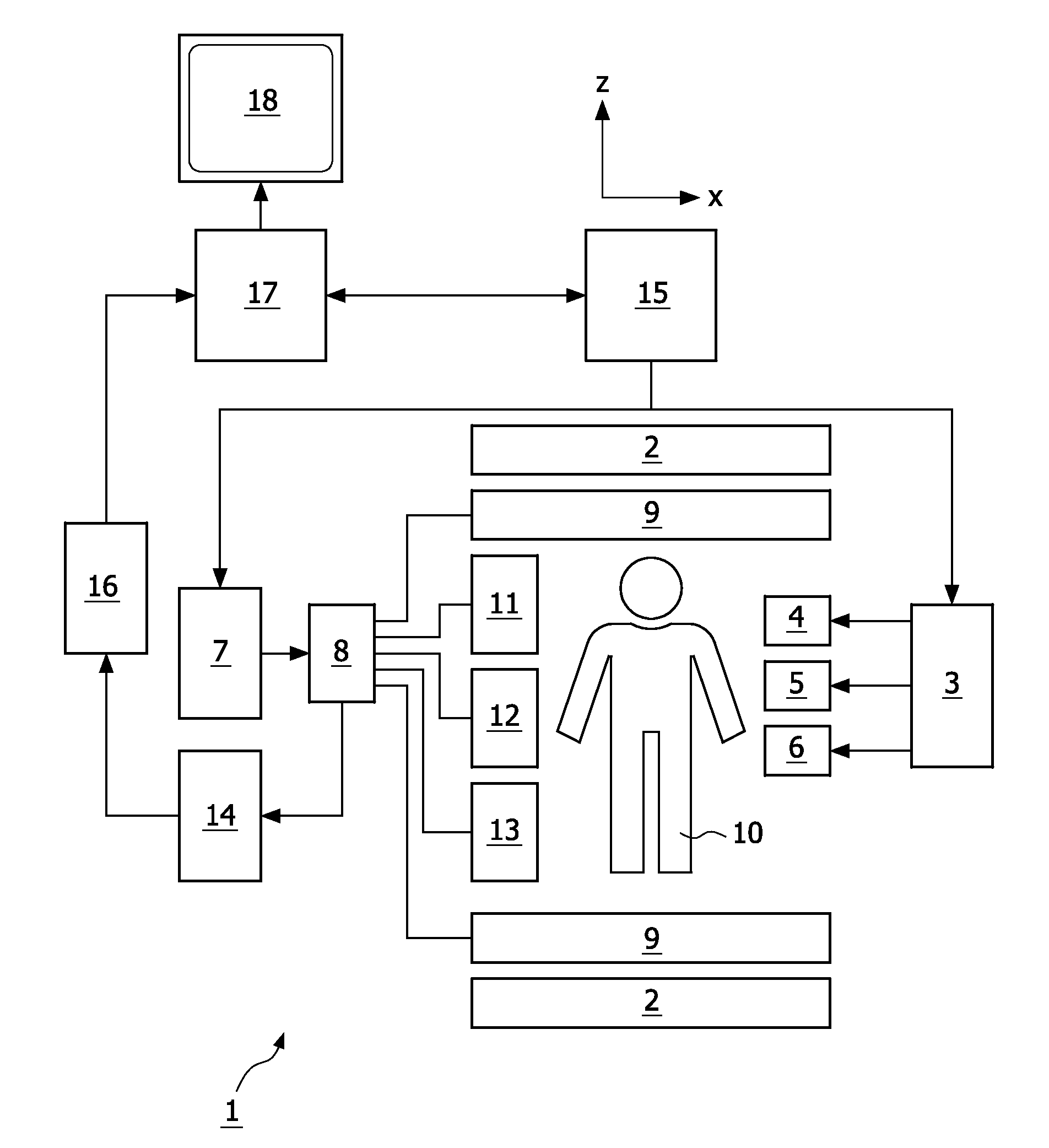
[0025]With reference to FIG. 1, an MR device 1 is shown. The device comprises superconducting or resistive main magnet coils 2 such that a substantially uniform, temporally constant main magnetic field is created along a z-axis through an examination volume.

[0026]A magnetic resonance generation and manipulation system applies a series of RF pulses and switched magnetic field gradients to invert or excite nuclear magnetic spins, induce magnetic resonance, refocus magnetic resonance, manipulate magnetic resonance, spatially and otherwise encode the magnetic resonance, saturate spins, and the like to perform MR imaging.

[0027]Most specifically, a gradient pulse amplifier 3 applies current pulses to selected ones of whole-body gradient coils 4, 5 and 6 along x, y and z-axes of the examination volume. A digital RF frequency transmitter 7 transmits RF pulses or pulse packets, via a send- / receive switch 8, to a whole-body volume RF coil 9 to transmit RF pulses into the examination volume. A...


PUM


Abstract

The invention relates to a method of MR imaging of at least a portion of a body (10) of a patient placed in an examination volume of an MR device (1). The acquisition of high-resolution three-dimensional FLAIR images as well as T2-weighted images at high main magnetic field strength (>3 Tesla) results in unacceptable long scan times. The present invention contemplates a new and improved MR imaging method which overcomes this problem. The method of the invention comprises the steps of subjecting the portion of the body (10) to a first imaging sequence (S1) for acquiring a first signal data set; immediately subsequent to the first imaging sequence (S1) subjecting the portion of the body (10) to an inversion RF pulse that inverses longitudinal magnetization within the portion; after an inversion delay period (TI) subjecting the portion of the body (10) to a second imaging sequence (S2) for acquiring a second signal data set; reconstructing first and second MR images from the first and second signal data sets respectively.

Description

FIELD OF THE INVENTION[0001]The invention relates to the field of magnetic resonance (MR) imaging. It concerns a method of MR imaging of at least a portion of a body of a patient placed in an examination volume of an MR device. The invention also relates to an MR device and to a computer program to be run on an MR device.BACKGROUND OF THE INVENTION[0002]Image-forming MR methods which utilize the interaction between magnetic fields and nuclear spins in order to form two-dimensional or three-dimensional images are widely used nowadays, notably in the field of medical diagnostics, because for the imaging of soft tissue they are superior to other imaging methods in many respects, do not require ionizing radiation and are usually not invasive.[0003]According to the MR method in general, the body of the patient to be examined is arranged in a strong, uniform magnetic field whose direction at the same time defines an axis (normally the z-axis) of the co-ordinate system on which the measure...

Claims


Application Information

Patent Timeline
IPC IPC(8): A61B5/055
CPCG01R33/543G01R33/5602G01R33/563G01R33/5617G01R33/5611
Inventor VISSER, FREDERIK
Owner KONINKLIJKE PHILIPS ELECTRONICS NV
Why Eureka
Try Eureka