Prewarming Gown

a pre-warming gown and body technology, applied in the field of pre-warming gowns, can solve the problems of increasing the core temperature, reducing comfort, and thus sweating, and restricting patient mobility by full-body blankets, so as to reduce the increase in core temperature, and maintain the effect of core temperature constan

Active Publication Date: 2012-03-01
THE SURGICAL INT
View PDF61 Cites 29 Cited by
  • Summary
  • Abstract
  • Description
  • Claims
  • Application Information

AI Technical Summary

Benefits of technology

[0011]The distributor is connectable to an air hose. The distributor inflates when forced, heated air is supplied and pushes the heated air throughout the inside of the gown. Air temperature is maintained at a desired level for the extremities, while also preventing the chest or thorax area from being increased to an uncomfortable level. The air temperature of the patient can be maintained within the gown before, during, or after surgery or any other medical procedure.
[0012]In such an embodiment as described above, the prewarming gown heats the limbs to prevent redistribution hypothermia and for optimal heat storage in the patient's body. Forced air heated full body blankets are very effective in warming the limbs. However, no distinction is made to the thorax and the limbs. The heat flow to the thorax can lead to an increase of the core temperature and a reduction of comfort, and thus sweating. Furthermore, patient mobility is restricted by full body blankets. The disclosed prewarming system operates to reduce the core-to-peripheral temperature gradient to prevent redistribution hypothermia, and also to increase the heat content of peripheral compartments (heat accumulation) to compensate for the heat loss during anesthesia.
[0013]The prewarming system includes a full body gown, integrated tube shape flow distributer, a blower, and a corrugated hose. The gown combines passive insulation by reflective fabric with forced air warming. The combination of reduced heat loss and active heat supply results in an increase of the peripheral compartment's heat content and temperature.
[0015]Medical requirements for the gown prescribe that the heated air flowing through the gown must be above 36° C. to prevent hypothermia. Heated forced air is created in a compact blower with a high rpm fan and a heat exchanger. To prevent unintended cooling of the patient, the output temperature of the blower is adjusted to a range of 36-43° C. The patient can adjust the output volume flow of the blower manually to a comfortable level. The compact blower is supplied with a bed mounting mechanism. By means of an optional battery pack, the blower can be kept in operation while the patient is transported.
[0018]The fabric of the gown is supplied with a reflective coating (such as alumina) at the arms, legs, and back to reduce the heat loss by radiation. The fabric at the thorax is uncoated to reduce the increase in core temperature due to the supplied heated air.
[0019]The prewarming system distinguishes itself from other prewarming systems in effective heating of the legs and arms while maintaining a constant core temperature. Furthermore, the patient's freedom of movement is not restricted as with heated mattresses and blankets. Besides prewarming, the gown provides patient warming during surgery and during postoperative warming. The seam at the back portion of the gown is openable such that the gown can be draped more optimally during treatment.

Problems solved by technology

The heat flow to the thorax can lead to an increase of the core temperature and a reduction of comfort, and thus sweating.
Furthermore, patient mobility is restricted by full body blankets.

Method used


Image

  • Prewarming Gown
  • Prewarming Gown
  • Prewarming Gown

Examples


fourth embodiment

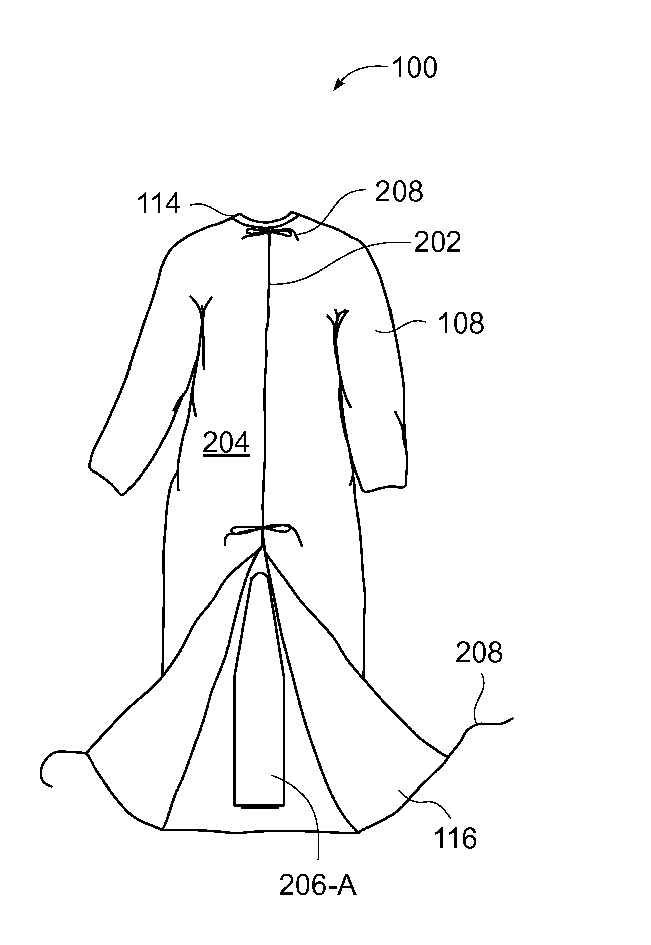
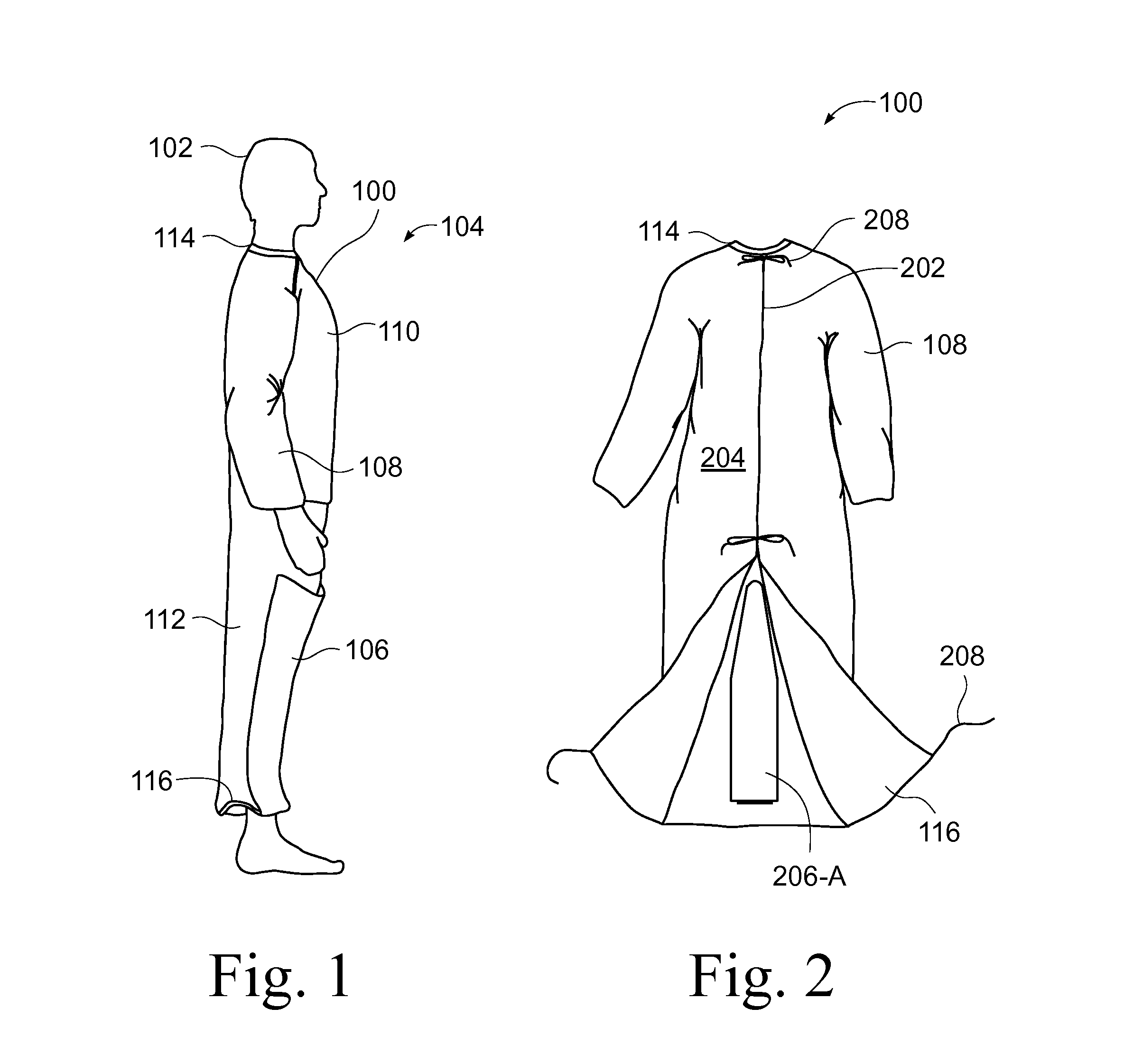
[0080]FIG. 11 illustrates a lateral view of a distributor 206-D for the gown 100. In the illustrated embodiment, the distributor 206-D is accessed through the drape 106 of the gown. The distributor 206-D extends from the drape 106, past the feet, between the legs, and toward the crotch area of the patient 102.

[0081]In the passive configuration, the distributor 206-D is deflated and rests against a portion of the drape 106 and the inside anterior surface of the leg portion 112 of the gown 100. The base 606 at the proximal end of the distributor 206-D is attached to the inside surface of the drape 106. The distal end of the distributor 206-D is attached to the inside anterior surface of the leg portion 112. In one embodiment, the proximal end of the distributor 206-D is tethered to the inside surface of the drape 106 in the region proximate the hem 116. When the drape is in the stowed position, the deflated distributor 206-D folds or rolls with the drape 106.

[0082]As discussed above i...

fifth embodiment

[0083]FIG. 12 illustrates a lateral view of a distributor 206-E for the gown 100. In the illustrated embodiment, the distributor 206-E has a first section 1202 and a second section 1204 joined at a seam 1206. The first section 1202 is substantially external to the gown 100 and is not air permeable. The second section 1204 is internal to the gown 100 and is air permeable.

[0084]The proximal end of the first section 1202 of the distributor 206-E is attached to the outside anterior surface of the leg portion 112 proximate the hem 116 of the gown 100. The first section 1202 of the distributor 206-E extends through a slit 1208 to the inside of the gown 100. The slit 1208 is located proximate the hem 116 in the leg portion 112 of the gown 100 and is positioned substantially between where the legs of the patient 102 contact the leg portion of the gown 100 with the patient's feet shoulder width apart. The second section 1204 of the distributor 206-E is located within the gown 100 and extends...

sixth embodiment

[0087]FIG. 13 illustrates a lateral view of a distributor 206-F for the gown 100. In the illustrated embodiment, the gown 100 includes an inner layer 1302 adjacent the drape 106 and the leg portion 112. The inner layer 1302 is air permeable. The peripheral edge of the inner layer 1302 is joined to the drape 106 and the leg portion 112 of the gown 100, which are not air permeable, to create a distributor or chamber 206-F. The inner layer 1302 is joined to the drape 106 proximate the distal end of the drape 106. The inner layer 1302 extends toward the waist of the patient 102. In one embodiment, the inner layer 1302 is joined to the leg portion 112 proximate the crotch area of the patient 102. In one embodiment, the chamber 206-F is between the legs of the patient 102, and extends from the region proximate the distal end of the drape 106 towards the crotch area of the patient 102. In another embodiment, the distributor 206-F has a width that extends past the legs of the patient 102 su...


PUM


Abstract

A device for warming a human body. The device is a gown that has a body with a thorax portion and a leg portion. One embodiment prevents redistribution hypothermia with a distributor attached to the inside of the leg portion. The sleeves, leg portion, and posterior of the gown are heat reflective. The anterior of the thorax portion of the gown is non-reflective. The distributor inflates when heated air is supplied. The distributor exhausts air into the gown. Temperature is maintained at a desired level for the extremities, while preventing the thorax area from being elevated to an uncomfortable level. Another embodiment is a perioperative warming device. The device is a gown that has a thorax portion and a leg portion. Each portion has an independent air chamber and inlet. The two portions are releasably connected. The sleeves, leg portion, and anterior of the gown are heat reflective.

Description

CROSS-REFERENCE TO RELATED APPLICATIONS[0001]This application claims the benefit of U.S. Provisional Application No. 61 / 378,245, filed Aug. 30, 2010.STATEMENT REGARDING FEDERALLY SPONSORED RESEARCH OR DEVELOPMENT[0002]Not ApplicableBACKGROUND[0003]1. Field of Invention[0004]This invention relates to a system for warming the body of a human. More particularly, this invention pertains to passive warming and active warming before, during, and after surgery or other medical procedures.[0005]2. Description of the Related Art[0006]Inflatable thermal blankets that are used to communicate a conditioned gas, such as heated or cooled air, to a patient are known in the art. Such thermal blankets typically have an inflatable portion provided with an inlet port for placing the inflatable portion in fluid communication with a source of pressurized, conditioned gas such that the inflatable portion can be selectively inflated. The inflatable portion generally has an inner surface that is positioned...

Claims


Application Information

Patent Timeline
Patent Type & Authority Applications(United States)
IPC IPC(8): A41D13/12
CPCA61F7/0097A61F7/02A61F2007/006A61F7/0085A61F2007/0236A61F2007/0257A61F2007/0258A61F2007/0234
Inventor VAN OUDENALLEN, ROBERTUS GERARDUSTEUNISSEN, BEREND JAN
Owner THE SURGICAL INT
Why Eureka
Try Eureka