

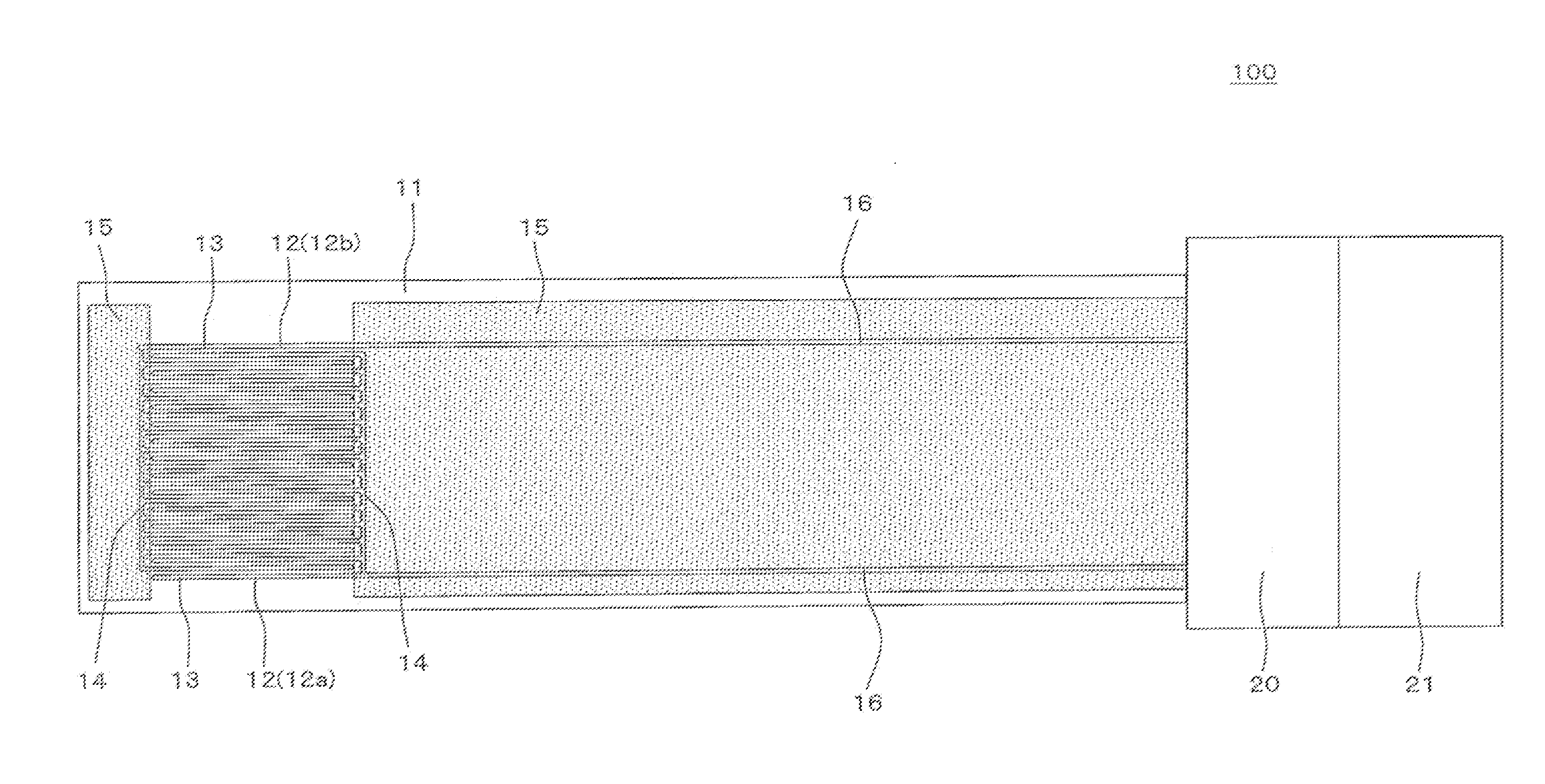
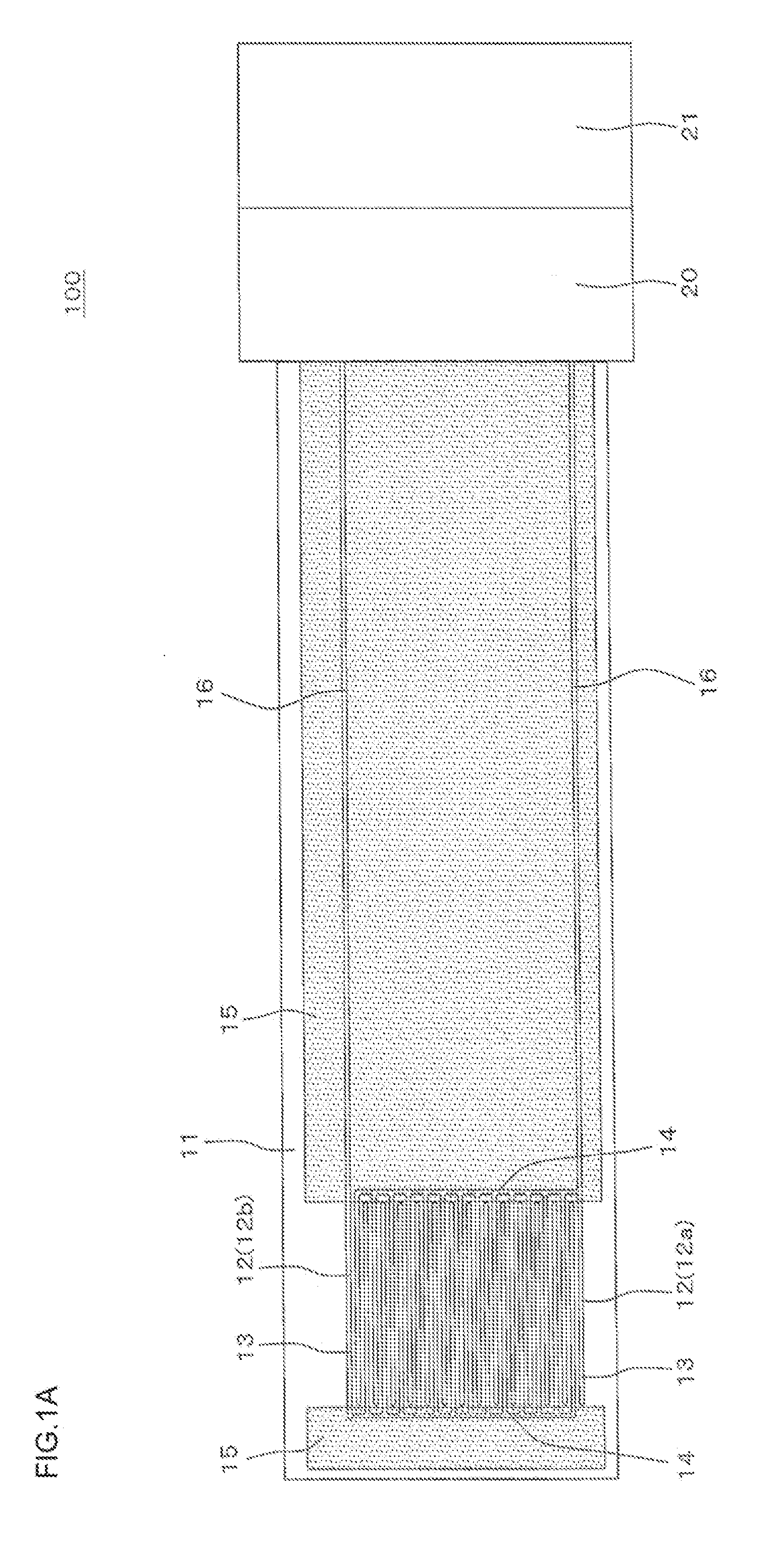
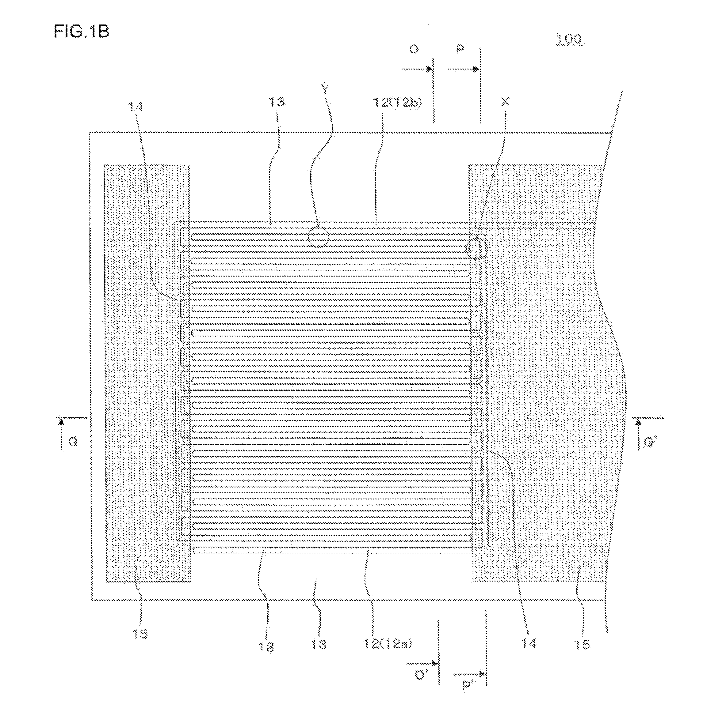
Particulate matter detection device
a detection device and particle technology, applied in measurement devices, instruments, scientific instruments, etc., can solve the problems of disturbing the enhancement of measurement accuracy of the device, and the measurement sensitivity of the device is still not satisfactory, so as to achieve accurate detection, reduce thickness, and improve measurement accuracy
- Summary
- Abstract
- Description
- Claims
- Application Information
AI Technical Summary
Benefits of technology
Problems solved by technology
Method used
Image

Examples
example 1
[0155](Preparation of Forming Raw Material)
[0156]As a dielectric raw material, alumina was used, as a binder, polyvinyl butyral was used, as a plasticizer, di-2-ethyl hexyl phthalate was used, as a dispersant, sorbitan tri-oleate was used, and as a dispersion medium, an organic solvent (xylene:butanol=6:4 (mass ratio)) was used. These materials were put into a pot made of alumina, and mixed, to prepare a slurried forming raw material for preparing a green sheet. Amounts of the raw materials for use were 7 parts by mass of the binder, 3.5 parts by mass of the plasticizer, 1.5 parts by mass of the dispersant and 100 parts by mass of the organic solvent with respect to 100 parts by mass of alumina.
[0157]Next, the obtained slurried forming raw material for preparing the green sheet was stirred and defoamed under a reduced pressure, and prepared so as to obtain a viscosity of 4 Pa·s. The viscosity of the slurry was measured with a B-type viscosity meter.
[0158](Forming Processing)
[0159]Ne...
PUM
| Property | Measurement | Unit |
|---|---|---|
| thickness | aaaaa | aaaaa |
| thickness | aaaaa | aaaaa |
| thickness | aaaaa | aaaaa |
Abstract
Description
Claims
Application Information