Bifacial solar cell module

a solar cell and module technology, applied in the field of bifacial solar cell modules, can solve the problems of low current conversion efficiency of common solar cells, and achieve the effects of reducing the thickness of the module, reducing the decolorization problem of the seal member due to ultraviolet ray exposure, and improving the output of the solar cell modul

Inactive Publication Date: 2012-03-01
LG ELECTRONICS INC
View PDF7 Cites 22 Cited by
  • Summary
  • Abstract
  • Description
  • Claims
  • Application Information

AI Technical Summary

Benefits of technology

[0021]Particularly, ETFE used as the first substrate or the second substrate has light transmittance of average 90% or more and light absorptance of 1% or less in a wavelength band of 400 nm or more and can be thus matched to a high light transmittance of a seal member without light damage. Therefore, when the substrate made of ETFE is used as a back sheet, light is effectively applied through the substrate and thus an efficiency of the bifacial solar cell module increases.
[0033]Further, because the silicone resin has a low curing temperature, a modularization process can be performed at a lower temperature and curing time can be shortened.

Problems solved by technology

Therefore, because light is applied through only one side surface of the substrate, a common solar cell has low current conversion efficiency.

Method used


Image

  • Bifacial solar cell module
  • Bifacial solar cell module
  • Bifacial solar cell module

Examples


Embodiment Construction

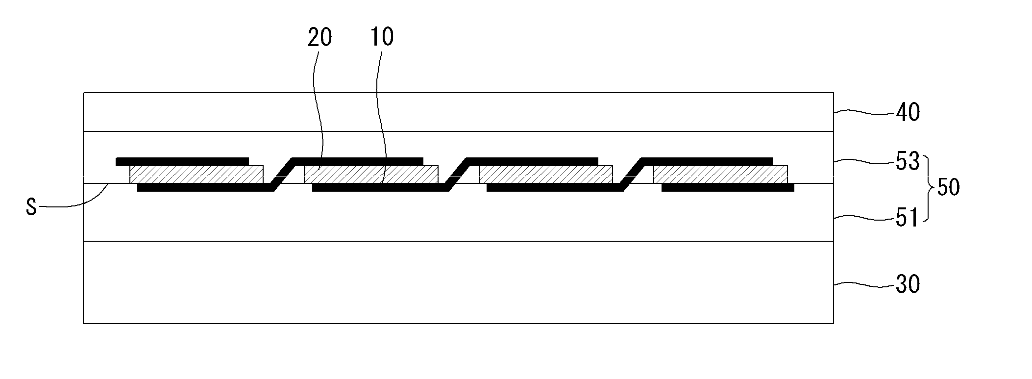
[0048]In the following detailed description, only certain implementations of this document have been shown and described, simply by way of illustration. As those skilled in the art would realize, the described implementations may be modified in various different ways, all without departing from the spirit or scope of this document. Accordingly, the drawings and description are to be regarded as illustrative in nature and not restrictive. Like reference numerals designate like elements throughout the specification.

[0049]In the drawings, the thickness of layers, films, panels, regions, etc., are exaggerated for clarity. When it is said that any part, such as a layer, film, region, or plate, is positioned on another part, it means the part is directly on the other part or above the other part with at least one intermediate part. In contrast, when an element is referred to as being “directly on” another element, there are no intervening elements present.

[0050]Further, when any portion i...


PUM


Abstract

A bifacial solar cell module comprises: a plurality of bifacial solar cells; a light transmitting first substrate positioned at a first surface side of the bifacial solar cells; a light transmitting second substrate positioned at a second surface side of the bifacial solar cells; and a seal member positioned between the first substrate and the second substrate and made of a sealing material of at least one layer, wherein at least one of the first substrate and the second substrate is made of an ethylene tetrafluoroethylene copolymer (ETFE) copolymer in which light transmittance is 85% or more and light absorptance is 5% or less in an entire wavelength band.

Description

CROSS-REFERENCE TO RELATED APPLICATION[0001]This application claims priority to and the benefit of Korean Patent Application No. 10-2011-0094422 filed in the Korean Intellectual Property Office on Sep. 20, 2011, the entire contents of which are incorporated herein by reference.BACKGROUND[0002]1. Field[0003]This document relates to a bifacial solar cell module.[0004]2. Related Art[0005]Photovoltaic power generation that converts light energy to electrical energy using photoelectric conversion effect is widely used as a means that obtains non-polluting energy. With improvement of photoelectric conversion efficiency of a solar cell, a photovoltaic power generation system using a plurality of solar cell modules can be installed in an individual house.[0006]A common solar cell comprises a substrate and an emitter forming a p-n junction with the substrate, and generates current using light applied through one side surface of the substrate.[0007]Therefore, because light is applied through ...

Claims


Application Information

Patent Timeline
Patent Type & Authority Applications(United States)
IPC IPC(8): H01L31/048
CPCH01L31/048Y02E10/547H01L31/068H01L31/0481H01L31/042
Inventor WOO, TAEKIYU, JEMINKIM, TAEYOONLEE, EUNJOOMUN, SEIYOUNGHONG, JONGKYOUNG
Owner LG ELECTRONICS INC
Why Eureka
Try Eureka