Gripper with carbon nanotube film structure

a carbon nanotube and film structure technology, applied in piezoelectric/electrostrictive/magnetostrictive devices, piezoelectric/electrostriction/magnetostriction machines, load-engaging elements, etc., can solve the problems of inability to actuate in the event, unattractive and impractical to present needs, and large number of parts, size and weigh

Active Publication Date: 2012-03-01
TSINGHUA UNIV +1
View PDF9 Cites 10 Cited by
  • Summary
  • Abstract
  • Description
  • Claims
  • Application Information

AI Technical Summary

Problems solved by technology

Currently technology for controlling these types of devices usually falls into actuator categories that could be unattractive and impractical to present needs.
Moreover, it cannot be actuated in the event of a power loss, and has a relatively large number of parts, size, and weight.
Solenoid actuators ar...

Method used


Image

  • Gripper with carbon nanotube film structure
  • Gripper with carbon nanotube film structure
  • Gripper with carbon nanotube film structure

Examples


Embodiment Construction

[0023]The disclosure is illustrated by way of example and not by way of limitation in the figures of the accompanying drawings in which like references indicate similar elements. It should be noted that references to “an” or “one” embodiment in this disclosure are not necessarily to the same embodiment, and such references mean at least one.

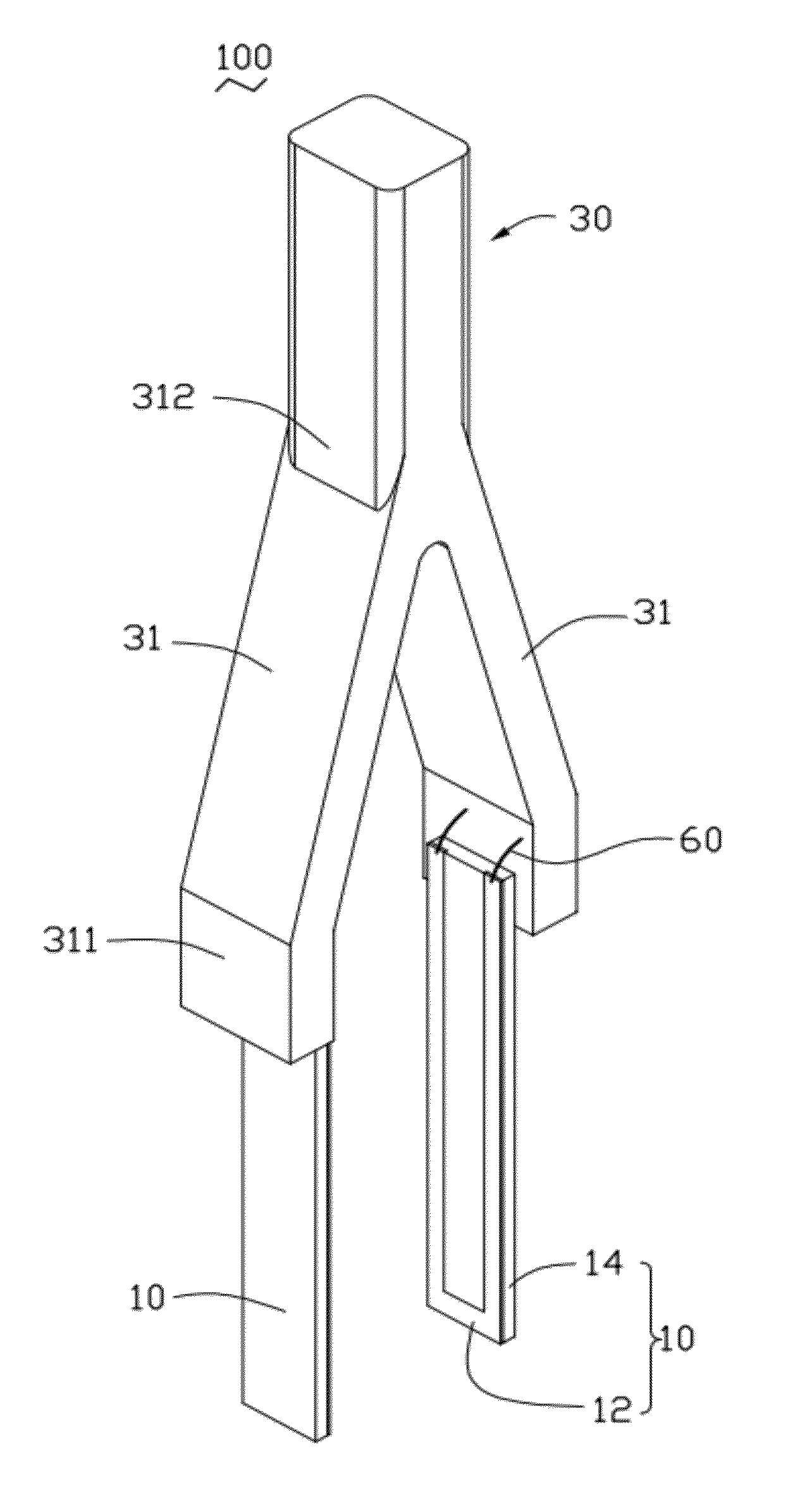
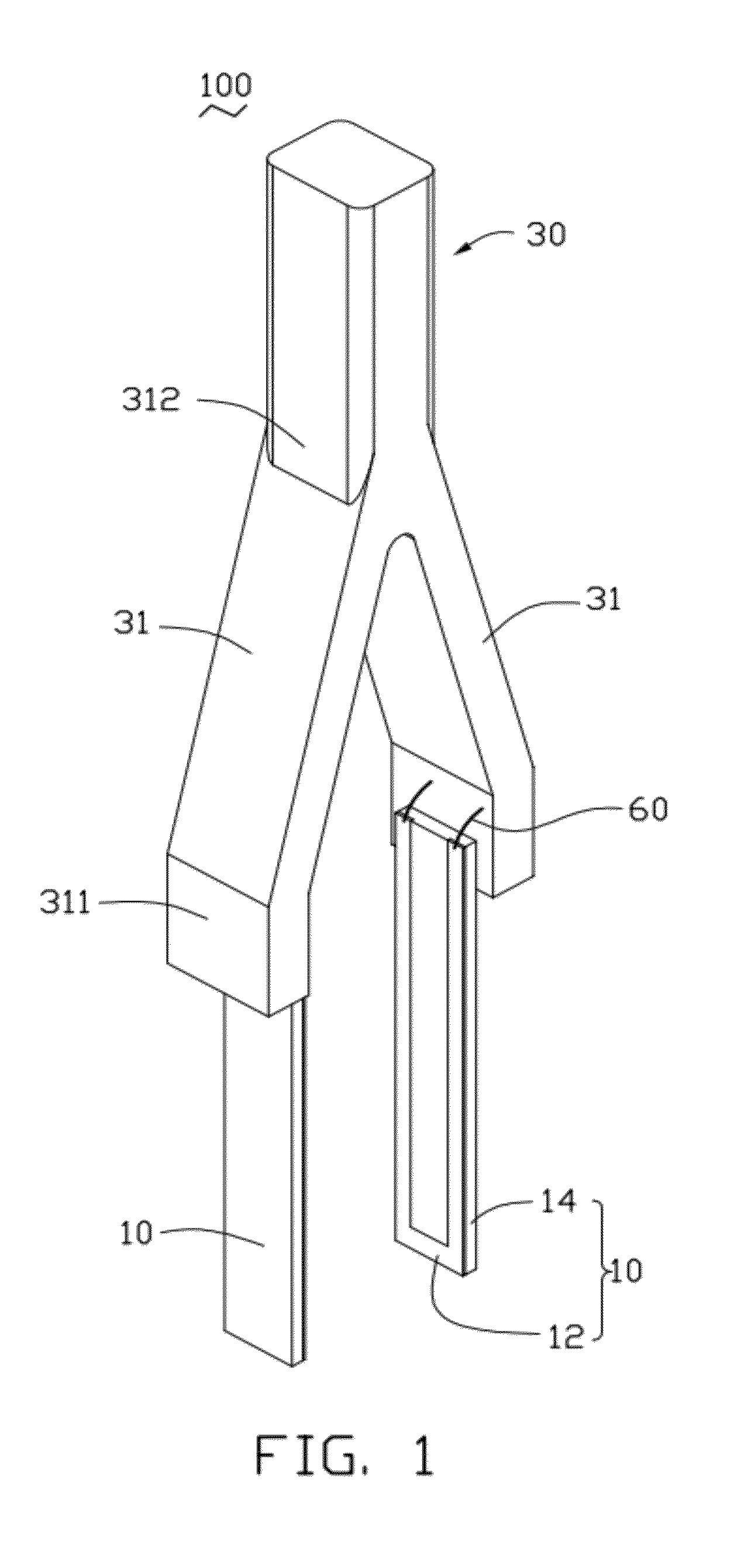
[0024]According to an embodiment, a gripper 100 as illustrated in FIG. 1 comprises a support 30, two gripping arms 10, and a plurality of conducting wires 60. The support 30 comprises two supportive arms 31. Each of the two supportive arms 31 comprises a first side 311 and a second side 312. The first sides 311 of the two supportive arms 31 are assembled opposing each other. The second sides 312 of the two supportive arms 31 are in contact with each other by integration or coherence. Thus, the support 30 is assembled as a Y-type support 30. The two gripping arms 10 are respectively fixed on the first sides 311 of the two supportive arms 31 by coh...


PUM


Abstract

A gripper includes a support and a plurality of gripping arms fixed on the support. One of the plurality of gripping arms includes a base and a carbon nanotube film structure to define a conductive circuit. The conductive circuit receives current to heat the base and the carbon nanotube film structure to actuate the gripper for gripping an object.

Description

BACKGROUND[0001]1. Technical Field[0002]The present disclosure relates to a gripper with a carbon nanotube film structure that receives current to actuate the gripper for gripping an object.[0003]2. Description of Related Art[0004]New devices and components for a wide variety of utility applications may require new packaging and deployment systems, such as object engagement and displacement mechanisms employed in medical instruments and semiconductor processing robotic components. Currently technology for controlling these types of devices usually falls into actuator categories that could be unattractive and impractical to present needs.[0005]For example, a DC motor-controlled gripper requires a second motor as an auxiliary (fail-safe mode) unit to ensure that the gripper will return to its open position. Moreover, it cannot be actuated in the event of a power loss, and has a relatively large number of parts, size, and weight. Solenoid actuators are essentially on / off devices, so th...

Claims


Application Information

Patent Timeline
IPC IPC(8): B25J15/02B25J15/00B66C1/44
CPCB25J7/00H01L21/68707B25J15/12
Inventor CHEN, LU-ZHUOLIU, CHANG-HONGFAN, SHOU-SHAN
Owner TSINGHUA UNIV
Why Eureka
Try Eureka