

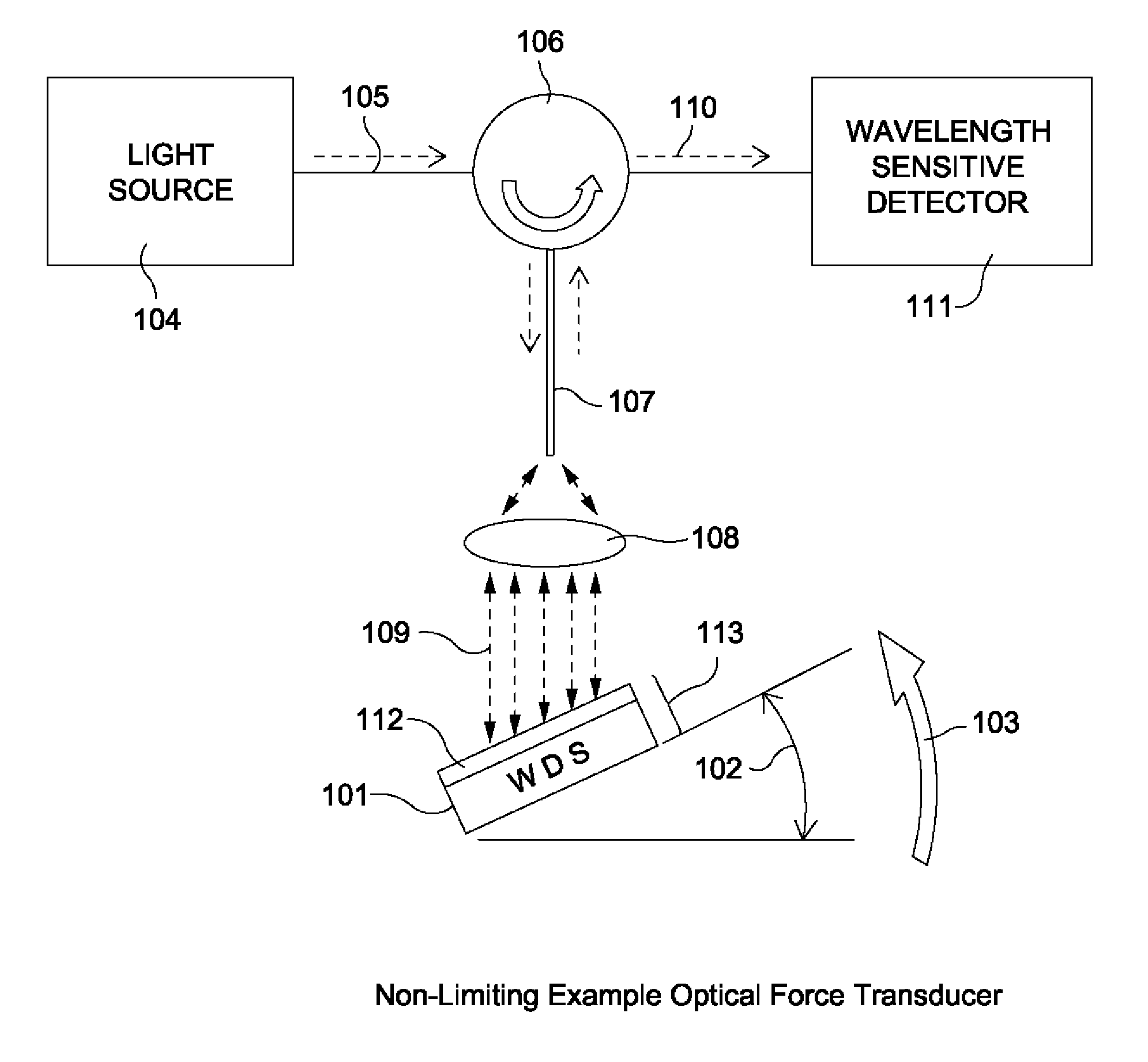
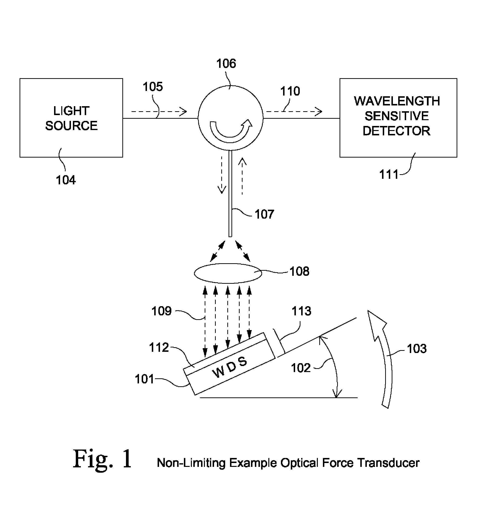
Wavelength dependent optical force sensing
a technology of optical force sensing and wavelength, applied in the direction of force measurement by measuring optical property variation, optical radiation measurement, instruments, etc., can solve the problems of intensity-based optical sensors, other sources of intensity loss interference, and difficult multiplication of fp sensors or sensors
- Summary
- Abstract
- Description
- Claims
- Application Information
AI Technical Summary
Benefits of technology
Problems solved by technology
Method used
Image

Examples
Embodiment Construction
Non-Limiting Introduction To Example Concepts And Arrangements
[0062]Because of the global power of the sensors and methods disclosed herein to measure many different measurands via the translation of applied forces from many different physical stimuli, combined with several methods of obtaining wavelength-encodable optical signals, it is advantageous to give the following non-limiting explanations of descriptive words, terms and concepts:
Fictitious Force: as Non-Limiting Examples, Centrifugal Force(s) and Change in Momentum
[0063]Wavelength-encoded signals: Signals from a single sensor can be assigned to a particular wavelength band over its wavelength range of operation. Different sensors can then be connected together, either in a single optical path (optically in series) or in different optical paths through an optical splitter (optically in parallel) or a combination of such paths. This method is sometimes also known as wavelength-division-multiplexing, or WDM.
[0064]Wavelength-de...
PUM
 Abstract
Description
Claims
Application Information