
Methods and systems for assessing residual life of turbomachine airfoils

Active Publication Date: 2012-03-01
GENERAL ELECTRIC CO
View PDF7 Cites 26 Cited by
  • Summary
  • Abstract
  • Description
  • Claims
  • Application Information

AI Technical Summary

Benefits of technology

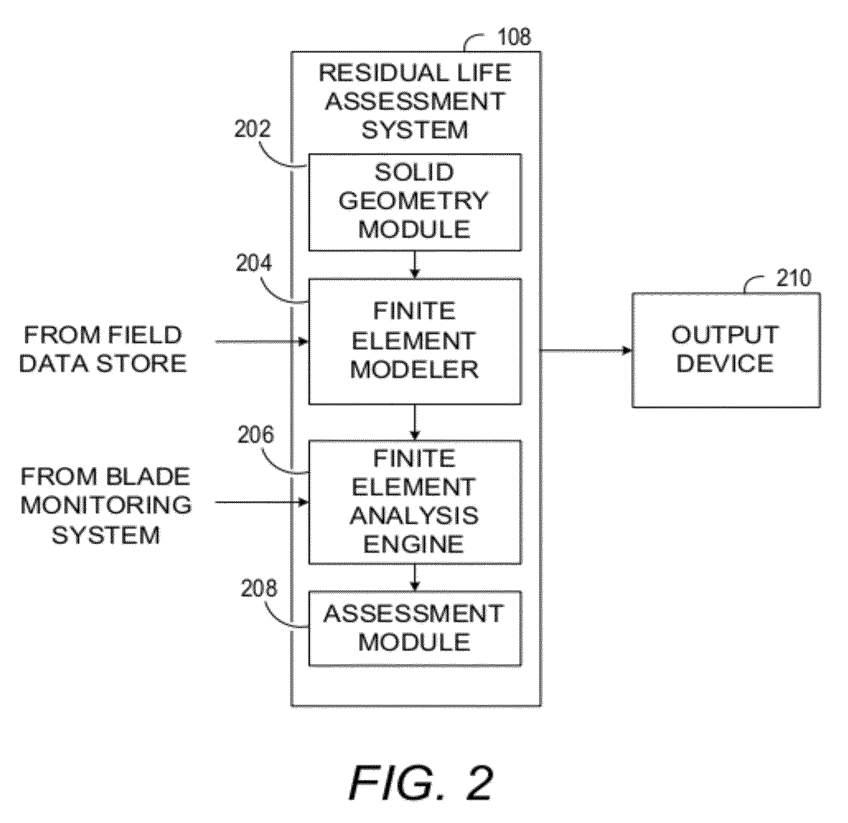
[0011]In accordance with another embodiment, a computer program product comprising a non-transitory computer readable medium encoded with computer-executable instructions for assessing residual life of an airfoil is provided. The computer-executable instructions, when executed, cause one or more processors to receive at least one vibration response parameter associated with the airfoil. The computer-executable instructions further cause the one or more processors to process at least one cracked airfoil finite element model. The processing includes accessing the cracked airfoil finite element model, computing a modal stress intensity factor (SIF) of the cracked airfoil finite element model using fracture mechanics based finite element analysis, and computing a vibratory SIF based, at least in part, on the modal SIF, and the at least one vibration response parameter. The computer-executable instructions then cause the one or more processors to compute a residual life indicator of the airfoil based, at least in part, on the vibratory SIFs.

Problems solved by technology

Turbine and compressor airfoils operate under extreme conditions and may develop cracks during normal operating conditions.
The cracks may develop due to high cycle fatigue, especially when a natural frequency of the airfoil matches the frequency of an excitation force experienced during normal turbomachinery operation.
Apart from known external disturbances, the turbomachinery may experience unanticipated excitations that match airfoil frequencies in normal service.
Such unanticipated excitations may cause the airfoil to resonate, thus exposing the airfoil to elevated amounts of vibration.
Such vibration may cause cracks to form on airfoils or airfoil supporting elements such as the platform and dovetails.
The cracks may propagate and rapidly extend due to the high cycle fatigue and vibration.
Neglected cracks in the turbomachine airfoils may lead to unplanned outages.
Some of these types of methods do not always yield sufficiently accurate results.
Often these types of methods may also not provide information about the underlying mechanism causing damage to a structural component, which may be critical in extending the residual life of the structural component.
Such techniques do not account for high cycle fatigue conditions, thus making such techniques unsuitable for assessing residual life under high cycle fatigue conditions.
However, such techniques are computationally intense and often require large amounts of computation capacity.

Method used


Image

  • Methods and systems for assessing residual life of turbomachine airfoils
  • Methods and systems for assessing residual life of turbomachine airfoils
  • Methods and systems for assessing residual life of turbomachine airfoils

Examples


Embodiment Construction

[0017]Embodiments presented herein provide methods, systems and computer program products for assessing residual life of turbomachine airfoils experiencing high cycle fatigue under conditions of at or near resonance vibration. In one embodiment, the method employs physics based 3D finite element analysis for computing residual life of an airfoil.

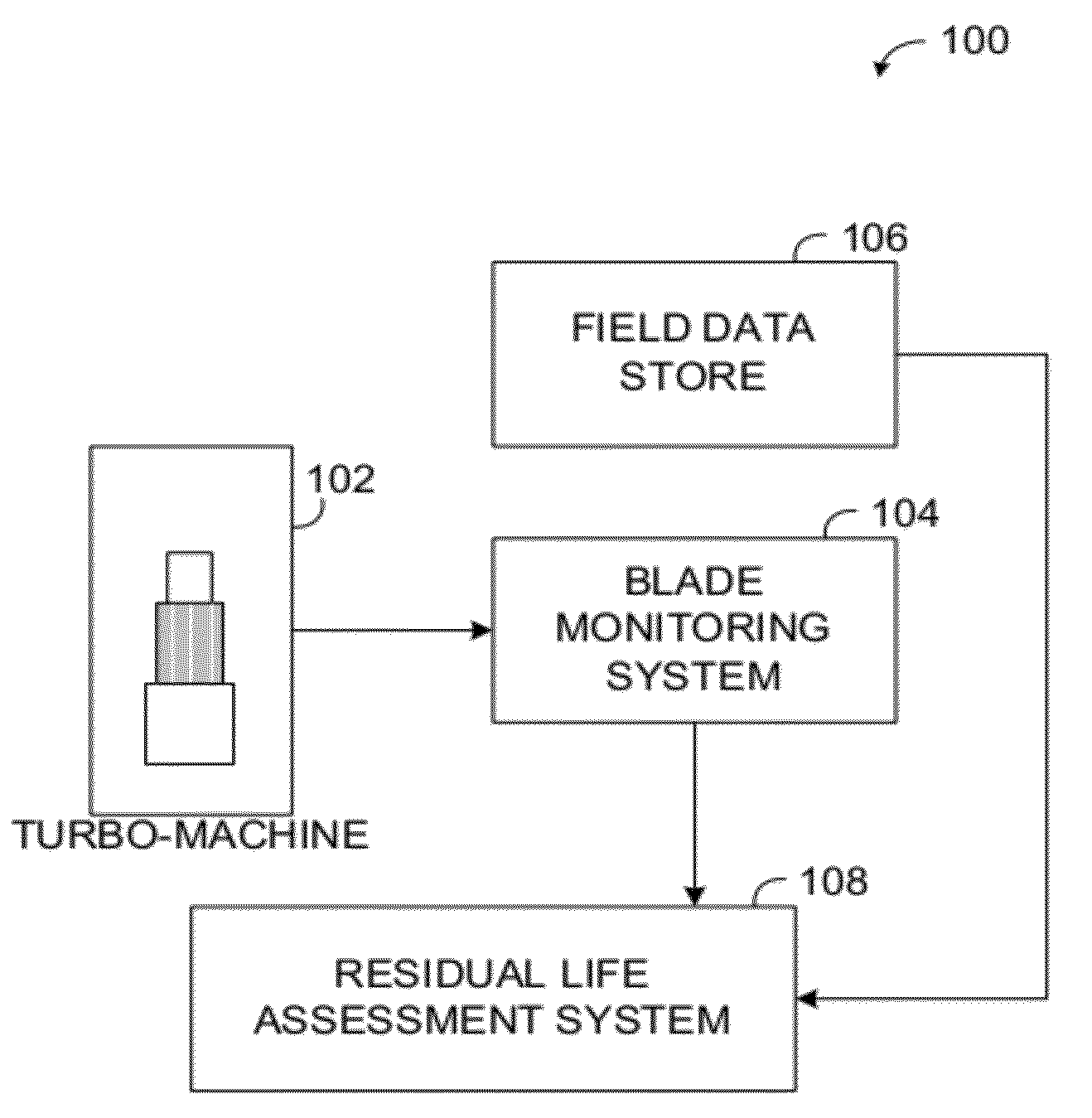
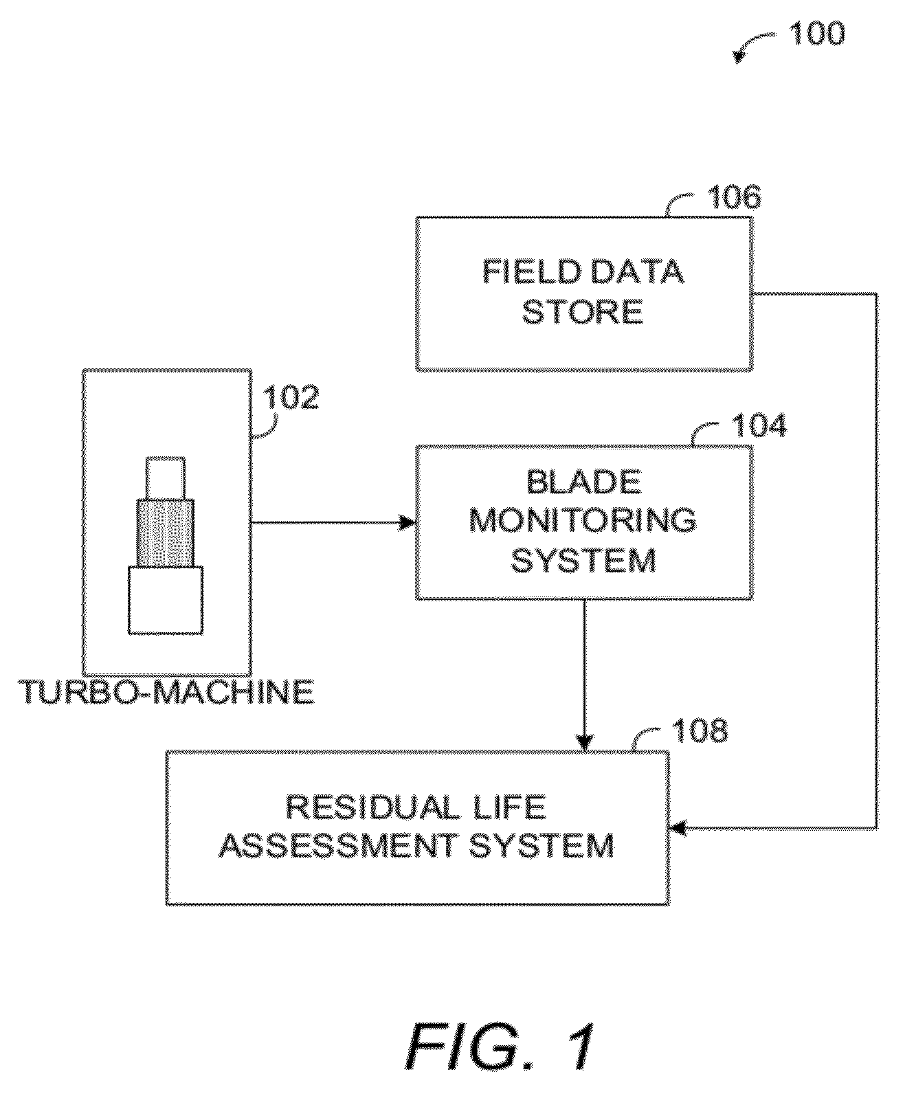
[0018]FIG. 1 illustrates an example environment 100 in which various embodiments may operate. Environment 100 includes a turbomachine 102, a blade monitoring system 104, a field data store 106, and a residual life assessment system 108. The turbomachine 102 may include, without limitation, a gas turbine engine, a steam turbine, and so forth.

[0019]The blade monitoring system 104 monitors operating conditions of a turbomachine airfoil, such as a compressor airfoil. The blade monitoring system 104 may monitor vibration response parameters such as, for example, blade vibration amplitude, blade vibration frequency, and airfoil structural damping....


PUM


Abstract

Methods, systems and computer program products for assessing residual life of an airfoil, which would experience high cycle fatigue failure under at- or near-resonance vibration condition, are provided. The method includes receiving, at a processing system, at least one vibration response parameter associated with the airfoil. The method processes at least one cracked airfoil finite element model. Processing the cracked airfoil finite element model includes accessing the cracked airfoil finite element model, computing a modal stress intensity factor (SIF) of the cracked airfoil finite element model using fracture mechanics based finite element analysis, and computing a vibratory SIF based, at least in part, on the modal SIF and the at least one vibration response parameter. The method then computes a residual life indicator of the airfoil based, at least in part, on the vibratory SIF.

Description

BACKGROUND[0001]Embodiments presented herein relate to residual life assessment of airfoils such as turbine rotors.[0002]Turbine and compressor airfoils operate under extreme conditions and may develop cracks during normal operating conditions. The cracks may develop due to high cycle fatigue, especially when a natural frequency of the airfoil matches the frequency of an excitation force experienced during normal turbomachinery operation. Power generation turbomachinery is typically exposed to external disturbances that have frequencies of 50 / 60 Hz and integral multiples of such frequencies. Airfoils used in such power generation machinery are designed to have a natural frequency different from the typical frequencies of external disturbances.[0003]Apart from known external disturbances, the turbomachinery may experience unanticipated excitations that match airfoil frequencies in normal service. Such unanticipated excitations may cause the airfoil to resonate, thus exposing the airf...

Claims


Application Information

Patent Timeline
IPC IPC(8): F01D25/00
CPCG01M5/0016G01M5/0033G06F17/50G06F17/5009G06F17/5018G01M5/0066G06F30/00G06F30/20G06F30/23
Inventor BAIK, SANGHUMBADAMI, VIVEK VENUGOPALPOTDAR, YOGESH KESRINATHLOGHIN, ADRIAN G.SHENG, NUO
Owner GENERAL ELECTRIC CO
Learn More