Methods and devices for wireless relays

a wireless relay and wireless technology, applied in the field of wireless relay networks, to achieve the effect of increasing the flexibility of the system, reducing the cost of operation, and increasing the throughput of data information

Inactive Publication Date: 2012-03-01
ALCATEL LUCENT SAS
View PDF15 Cites 19 Cited by
  • Summary
  • Abstract
  • Description
  • Claims
  • Application Information

AI Technical Summary

Benefits of technology

[0011]Obviously, when RN is introduced, it's very advantageous to propose a relay method which does not change existing UE. It is imperative for the relay method to ensure proper reception of data signal by UE in the relay channel; the same time sequence relation of data transmission and retransmitting feedback should be also ensured by the relay method, which should support HARQ retransmission mechanism and reduce waste of resource.
[0021]According to embodiments of the invention, different superior devices are responsible for send controlling signaling and data information respectively, which adds the flexibility of the system, for instance, the first base station obtains larger coverage for controlling signal by low-frequency carrier, while the second base station obtains larger throughput of data information by high-frequency carrier. The first or second base station or a communication collaborative device of the invention can be in charge of the collaborative control. Moreover, embodiments of the invention do not require much modification of UE and are of excellent backward compatibility.
[0022]According to preferred embodiments in relay technology of the invention, base station sends reference signals in each subframe, on the basis of which UE can estimate the channel completely; and base station can transmit controlling signaling e.g. retransmission feedback information to UE directly in each downlink subframe, which ensures the same time sequence relation between data transmission and retransmission feedback and supports HARQ retransmission mechanism and reduces waste of resource. In addition, preferred embodiment still set out that RN transmits data information on the basis of User-specific References signals (abbreviated as URS) or precoding, which causes that UE receives data information properly, meanwhile, no modification is required for UE and the invention are of excellent backward compatibility.

Problems solved by technology

Firstly the legacy UE is designed without consideration of relay, thus it can not be aware of the existence of relay station, which adds difficulty to the design of relay of LTE-Advanced.
Secondly, as relay concept is introduced, some uplink / downlink subframes or timeslots have to be reserved for Backhaul resources between base stations and relay stations. When relay stations receive data from base stations, such subframes or times lots are kept blank, which can not be used to transmit any symbols or data to UE, while present Release 8 assumes each subframe contains reference symbol, and UE estimates channels in a whole time-frequency grid by interpolating / averaging a plurality of reference symbols and reduce noise in channel estimation. It is expected that when UE measure reference symbols at downlink subframes which is preset to be blank, the zero value will be measured, which will result in error or failure of the whole channel estimation.
Thirdly, under the HARQ (Hybrid Automatic Repeat reQuest) mechanism, data transmission and ACK / NACK feedback have fixed timing relation. Because some uplink / downlink sub frames or timeslots are reserved for backhaul and cannot be used by UK, it may cause that after sender transmits codeword, no transmission of corresponding ACK / NACK feedback at anticipated subframes or timeslots is sent by the receiver side and no feedback is received at sender side consequently. The ACK / NACK collision may cause inefficient operation such as unnecessary retransmission. Such frequent “non-access” subframes lead to great difficulties to retain the fixed timing relation between HARQ transmission and ACK / NACK feedback. Furthermore, in each radio frame (10 ms for a period), the subframes #0, #4, #5 and #9 in FDD system and #0, #1, #5 and #9 in TDD system carry P-BCH (primary broadcast channel), P-SCH (Primary Synchronization Channel), S-SCH (Secondary Synchronization Channel), etc. for UE and thus can not be used for relay backhaul link, such limitation causes more difficulties to maintain HARQ timing.
The fake MBSFN subframe relay method has some defects (R1-090827): firstly, UE does not estimate the subframe configured as MBSFN subframe, which affects the continuity and integrality of the estimation.
Secondly, TDD time slot configurations will affect the efficiency of access link and performance of communication of the method, for instance, when an uplink subframe is used for the backhaul link transmission from RN to eNB, the subframe in access link must be configured as “MBSFN” and be blanked.
Consequently, after downlink data is transmitted in downlink subframe, the feedback of downlink data HARQ from UE in uplink subframe cannot be received by RN, which is expected to be received by RN originally, such HARQ feedback loss will lead to the waste of time-frequency resource, i.e. the downlink subframe can not transmit PDSCH.
The solution has some defects (3GPP RAN1 #56bis, March 2009): the solution is limited to assist HARQ to retransmit data only, rather than obtaining relay gain by high order modulation and coding of relay link of a relay communication method in general, moreover, only less than or equal to 30% of HARQ service requires retransmission according to statistics, so the utility efficiency of the solution is lower.
In addition, as for relay wireless network, channel quality between base station and UE is bad usually; while in R1-91403 solution, base station must communicate with UE by bad channel, in the scenario low order coding and modulation has to be assumed, therefore the communication between RN and UE must assume low order communication mode which is employed by base station also, thus the capacity based on the communication method is lower.

Method used


Image

  • Methods and devices for wireless relays
  • Methods and devices for wireless relays
  • Methods and devices for wireless relays

Examples


first embodiment

The First Embodiment

[0030]According to an aspect of the embodiment in the invention, the method of a first superior device and a second superior device collaboratively communicate with a subordinate device is specified as below.

[0031]In the embodiment, a first base station device eNB1 and a second base station device eNB2 collaboratively communicate with UE.

[0032]Firstly, eNB2 obtains transmission instruction information, which instructs eNB2 to transmit data information to UE in a preset subframe.

[0033]In one scenario, the transmission instruction information is provided by eNB1:[0034]eNB1 determines that eNB2 transmits data information to UE in a preset subframe;[0035]then eNB1 transmits the corresponding instruction information to eNB2.

[0036]In another scenario, the transmission instruction information is provided by a third party communication coordinating device:[0037]the communication coordinating device determines that eNB2 transmits data information to UE in a preset subfram...

second embodiment

The Second Embodiment

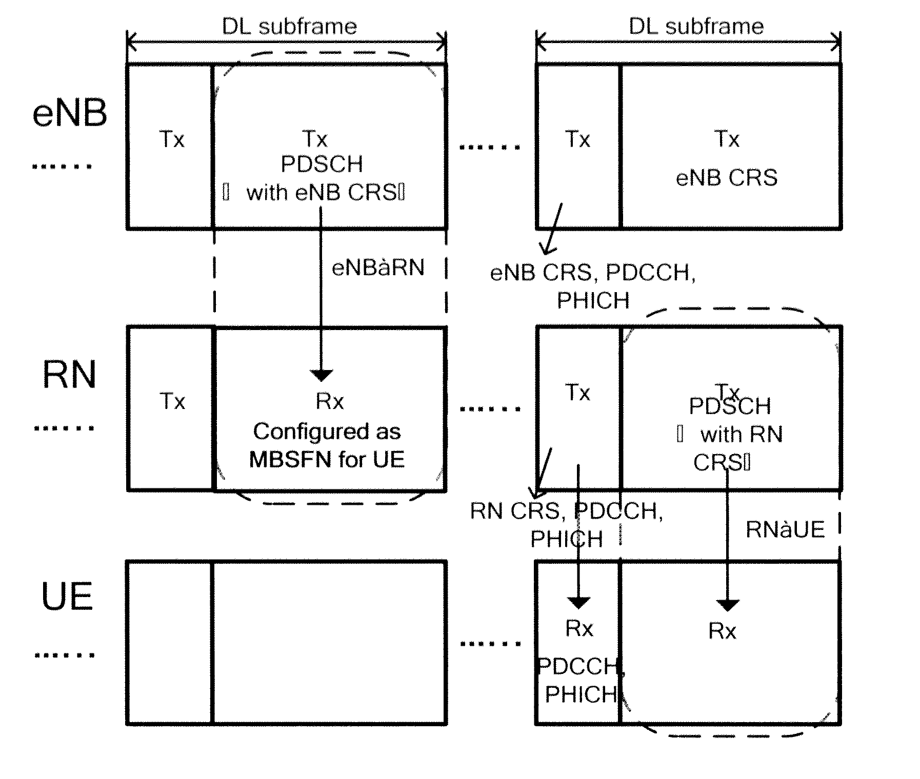
[0045]According to an embodiment of the invention, the process of that the RN relays the data information from eNB to UE, in a relay network based on LTE-A protocol, will be specified as below. It should be appreciated that the scenario mentioned does not limit the invention, and the invention is still applicable to other protocols and relay scenarios, for instance, RN2 relays the data information from RN1 to UE.

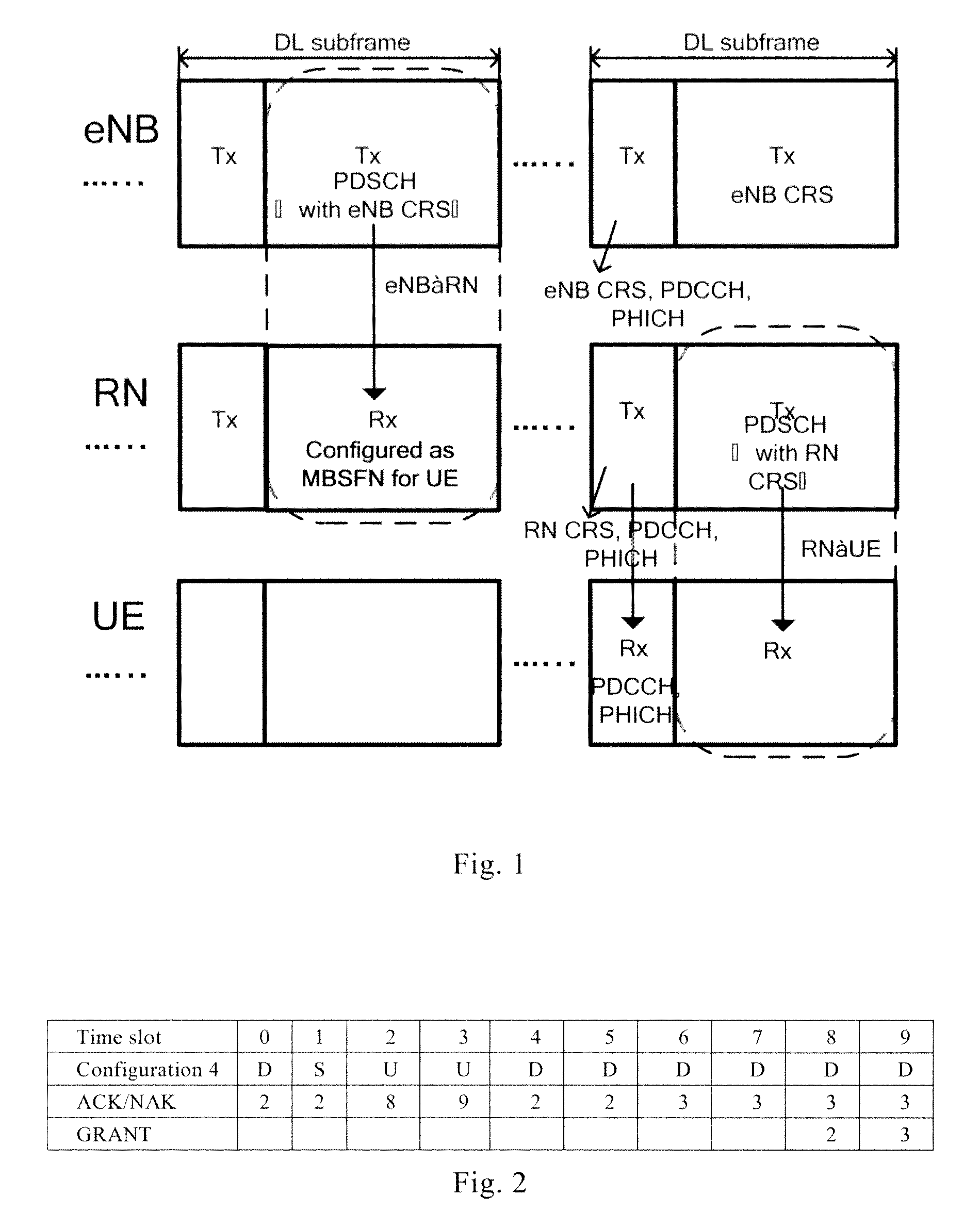
[0046]Firstly, in step of S1, by scheduling, eNB determines the preset subframe which is used for transmitting the data information from RN to UE, for instance, eNB schedules RN to transmit data information to UE in downlink subframe #2. Preferably, eNB further determines subcarrier, time slot, etc. in downlink subframe #2 which is used for transmitting the data information from RN to UE.

[0047]Later, in step of S2, eNB transmits transmission instruction information as a result scheduled by eNB to RN through a control channel e.g. PDCCH, the transmission ...

third embodiment

The Third Embodiment

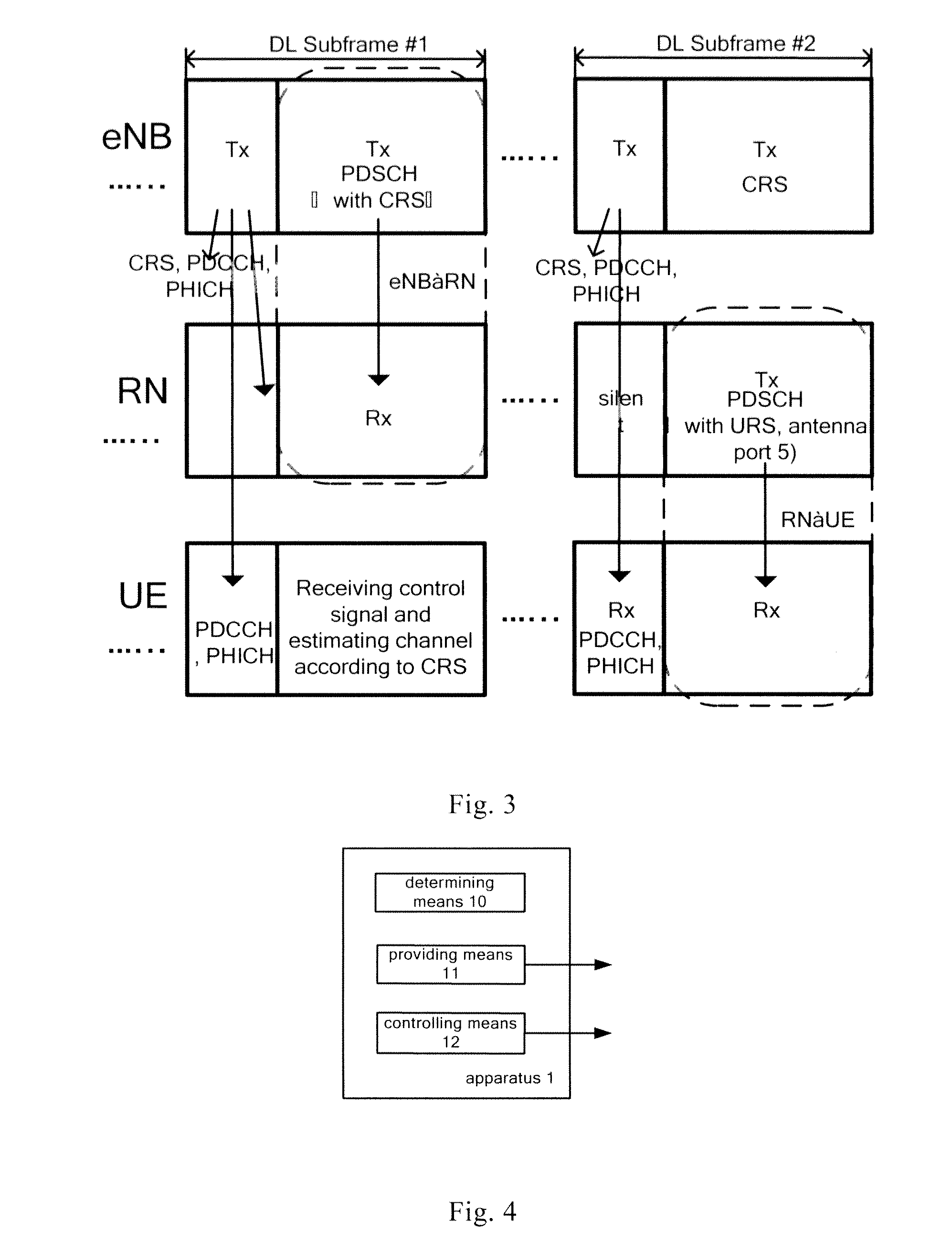
[0072]In the embodiment, the first base station device eNB1 and the second base station device eNB2 collaboratively communicate with UE. The first base station device eNB1 comprises an apparatus 1 which is used for communication with UE in cooperation with eNB2, the apparatus comprises a controlling means 12, and preferably further comprises a determining means 10 and a providing means 11. The second base station device eNB2 comprises an apparatus 2 which is used for communication with UE in cooperation with eNB1, the apparatus comprises an obtaining means 20 and a transmitter 21. In another scenario, the network still has a third party communication coordinating device, which comprises an apparatus 3 used for coordinating the first base station device eNB1 and the second base station to communicate with UE, and the apparatus comprises a determining means 30 and a providing means

[0073]Firstly, the obtaining means 20 of the second base station device eNB2 obtains ...


PUM


Abstract

A relay method and device, wherein the control signal and the data signal which are in the same subframe are directly sent to a lower level device respectively by an upper level device and a relay function device. In one example, the relay function device transmits data signal using subscriber special reference signal to make the lower level device estimate an access channel correctly; in another example, the relay function device carries out precoding of the data signal correlative with the access channel so as to cancel the influence of the access channel, thereby make the lower level device receive data signal correctly. Retransmission control signaling is sent to the lower level device in each subframe by the upper level device to ensure the fixed sequential relationship of feedback retransmission.

Description

FIELD OF THE INVENTION[0001]The present invention relates to wireless communication system, more particularly, to wireless relay network.BACKGROUND OF THE INVENTION[0002]The LTE-Advanced relay technology requires relay stations to provide backward compatibility for user equipments (abbreviated as UE) of Release 8, that is, LTE-Advanced relay scheme should support the legacy UE of Release 8 without any change to UE, in such case, there are some technical challenges accordingly:[0003]Firstly the legacy UE is designed without consideration of relay, thus it can not be aware of the existence of relay station, which adds difficulty to the design of relay of LTE-Advanced.[0004]Secondly, as relay concept is introduced, some uplink / downlink subframes or timeslots have to be reserved for Backhaul resources between base stations and relay stations. When relay stations receive data from base stations, such subframes or times lots are kept blank, which can not be used to transmit any symbols or...

Claims


Application Information

Patent Timeline
Patent Type & Authority Applications(United States)
IPC IPC(8): H04B7/14
CPCH04B7/15585H04L1/1835H04L1/1854H04W84/047H04L2001/0097H04W72/0406H04L1/1887H04W72/20H04B7/24H04B7/14H04L1/18
Inventor SHEN, GANGZHENG, WUWANG, DONGYAOLIU, JIMINWANG, WEIHAN, FENGJIANG, QI
Owner ALCATEL LUCENT SAS
Why Eureka
Try Eureka