Valve opening and closing mechanism
a valve and opening mechanism technology, applied in the direction of valve operating means/release devices, machines/engines, etc., can solve the problems of single power source gear and respective output shafts not being able to operate individually, wear and noise, and inability to accurately detect position, etc., to achieve the effect of suppressing the effects of vibration and gas pressure pulsation, reducing noise and wear, and reducing heat transmission
- Summary
- Abstract
- Description
- Claims
- Application Information
AI Technical Summary
Benefits of technology
Problems solved by technology
Method used
Image

Examples
first embodiment
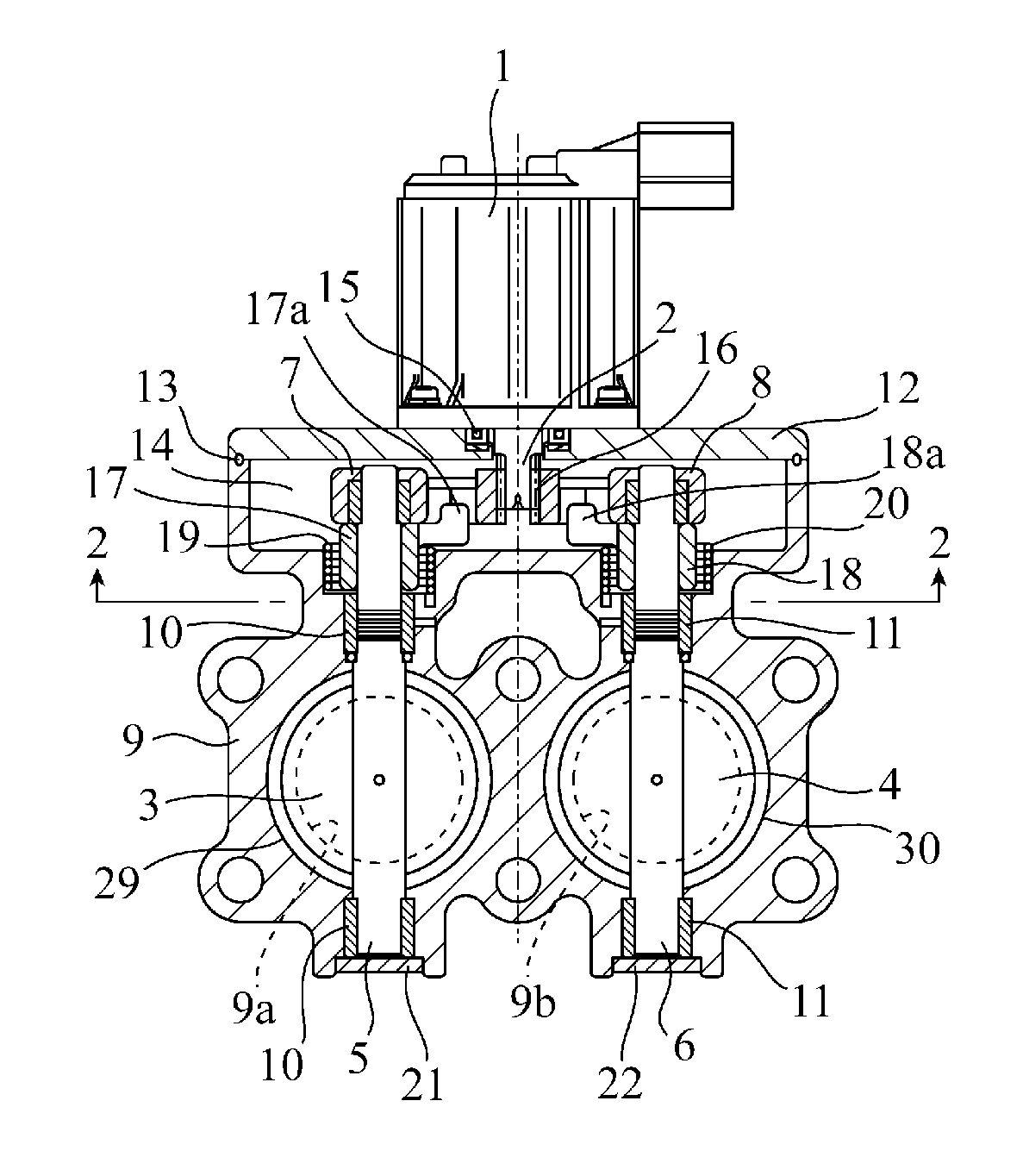
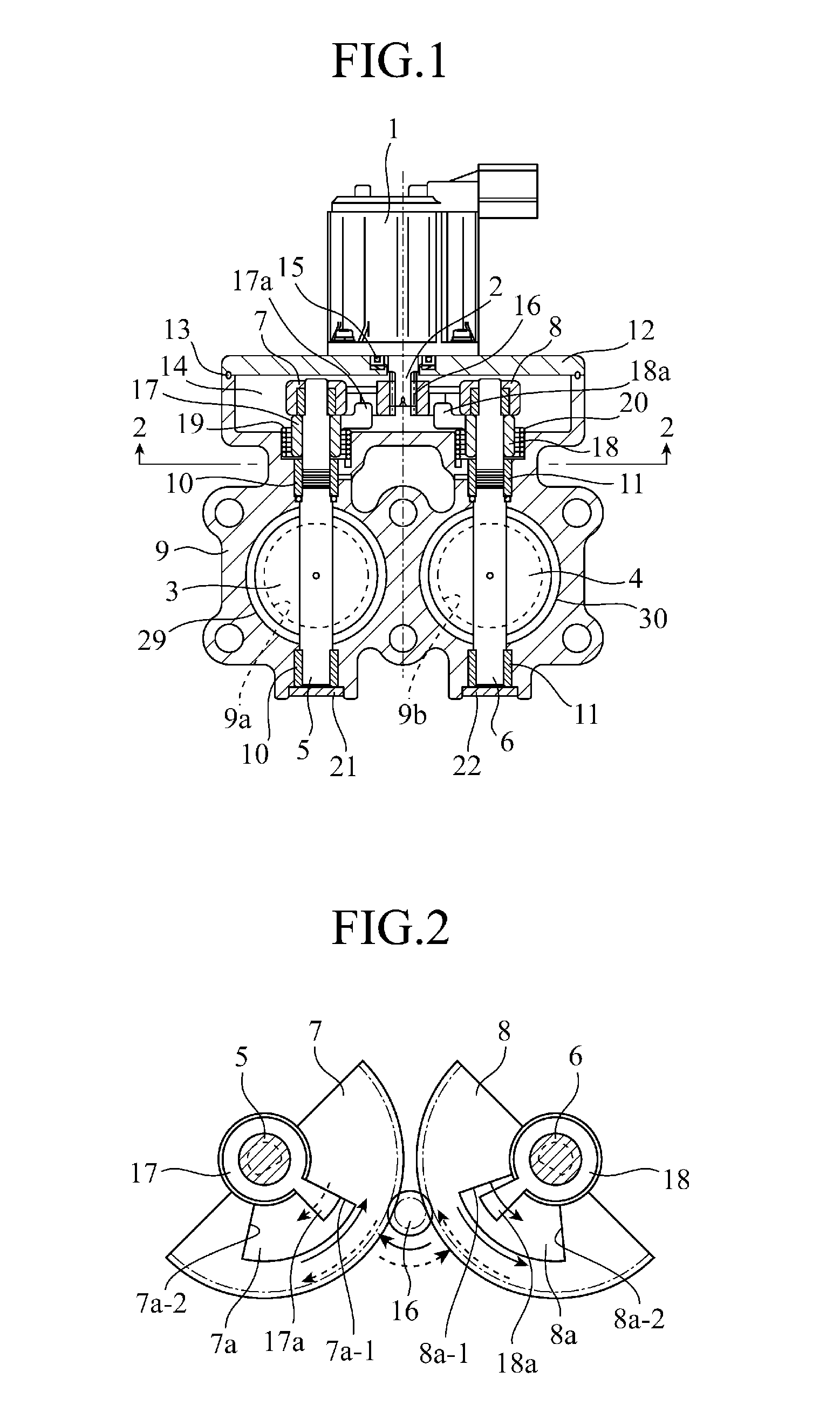
[0026]FIG. 1 is a constitutional diagram showing a partial longitudinal cross-section of a valve opening and closing mechanism according to a first embodiment of the present invention, and FIG. 2 is a transverse sectional bottom view taken along a line 2-2 in FIG. 1. This valve opening and closing mechanism includes a motor 1 serving as a power source, an input shaft 2 for inputting power from the motor 1 into a valve side, gears 7, 8 for transmitting the power from the input shaft 2 to output shafts 5, 6 respectively having valves 3, 4, and a valve housing 9 for housing these components and so on.
[0027]A passage 9a that passes through a cooler and a passage 9b that does not pass through the cooler are formed in the valve housing 9 in parallel. The output shafts 5, 6 are supported to be free to rotate via bearings 10, 11 so as to intersect and penetrate the passages 9a, 9b. An attachment substrate 12 of the motor 1 is attached via packing 13 to an upper end of a peripheral side wall...
second embodiment
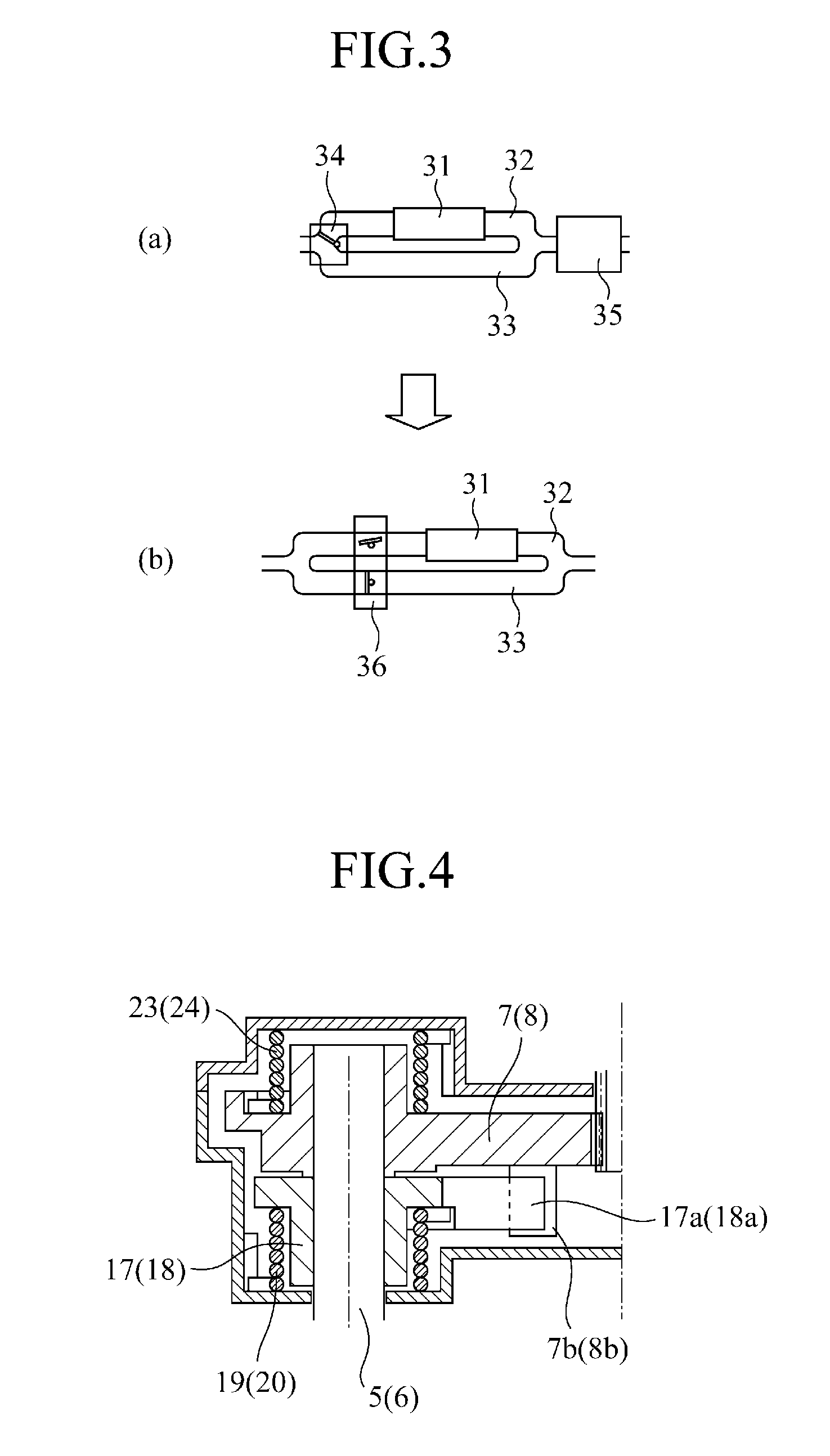
[0036]FIG. 4 is a longitudinal sectional constitutional view of a part showing a valve opening and closing mechanism according to a second embodiment of the invention. In this valve opening and closing mechanism, coil springs 23, 24 are attached respectively to the gears 7, 8 as preload application members such that preloads are applied to the gears 7, 8 in an opposite direction to the preloads applied to the output shafts 5, 6 by the coil springs 19, 20. In this case, one end of the coil springs 23, 24 is fixed to the gears 7, 8 and another end is fixed to the valve housing 9; thus, even when the motor 1 is not energized and the hole surfaces 7a-1, 8a-1 of the gears 7, 8 are not in contact with the arm members 17a, 18a, run-out of the gears 7, 8 can be suppressed due to the preloads applied by the coil springs 23, 24, and as a result, wear on the gears 7, 8 can be suppressed.
third embodiment
[0037]FIG. 5 is a longitudinal sectional constitutional view showing apart of the configuration of a valve opening and closing mechanism according to a third embodiment of the invention. In this valve opening and closing mechanism, a sensor 26 is disposed opposite a magnet 25 provided in a gear crown portion in order to increase a resolution. Specifically, the gear continues to move even when the valve on one side is inoperative, and therefore the gear does not run out relative to the output shaft even when positions of the respective valves are detected. Thus, when the sensor 26 is simply disposed opposite the magnet 25 in the gear crown portion on one side thereof, the positions of the valves on both sides can be detected. Note that when a valve is stuck or the like, the gear position and the valve position may not match, and therefore the sensor 26 may be disposed on the output shafts or the arm members on both sides opposite the magnets disposed in the gears.
PUM
 Abstract
Description
Claims
Application Information
 - R&D
- Intellectual Property
- Life Sciences
- Materials
- Tech Scout
- Unparalleled Data Quality
- Higher Quality Content
- 60% Fewer Hallucinations
Browse by: Latest US Patents, China's latest patents, Technical Efficacy Thesaurus, Application Domain, Technology Topic, Popular Technical Reports.
© 2025 PatSnap. All rights reserved.Legal|Privacy policy|Modern Slavery Act Transparency Statement|Sitemap|About US| Contact US: help@patsnap.com