Light-emitting device, illuminating device, vehicle headlamp, and method for producing light-emitting device

Active Publication Date: 2012-03-08
SHARP FUKUYAMA LASER CO LTD
View PDF1 Cites 67 Cited by
  • Summary
  • Abstract
  • Description
  • Claims
  • Application Information

AI Technical Summary

Benefits of technology

[0048]The above arrangement allows effective use of heat of the light emitting section, and thus eliminates the need to consume extra energy in order to, for example, thaw snow.
[0063]As described above, a light-emitting device of the present invention includes: an excitation light source for emitting excitation light; a light emitting section including a fluorescent material which emits light in response to the excitation light, the light emitting section having an excitation light irradiation surface which is irradiated with the excitation light; a light-transmitting heat conducting member which is provided so as to (i) face the excitation light irradiation surface and (ii) receive heat of the light emitting section; and a gap layer which fills a gap between the heat conducting member and the excitation light irradiation surface.
[0064]The above arrangement allows heat generated by the light emitting section to be efficiently dissipated with use of the heat conducting member.
[0065]As described above, a light-emitting device of the present invention includes: an excitation light source for emitting excitation light; a light emitting section which emits light in response to the excitation light; and

Problems solved by technology

Such a component easily raises a temperature of the light emitting section, and consequently im

Method used


Image

  • Light-emitting device, illuminating device, vehicle headlamp, and method for producing light-emitting device
  • Light-emitting device, illuminating device, vehicle headlamp, and method for producing light-emitting device
  • Light-emitting device, illuminating device, vehicle headlamp, and method for producing light-emitting device

Examples


Example

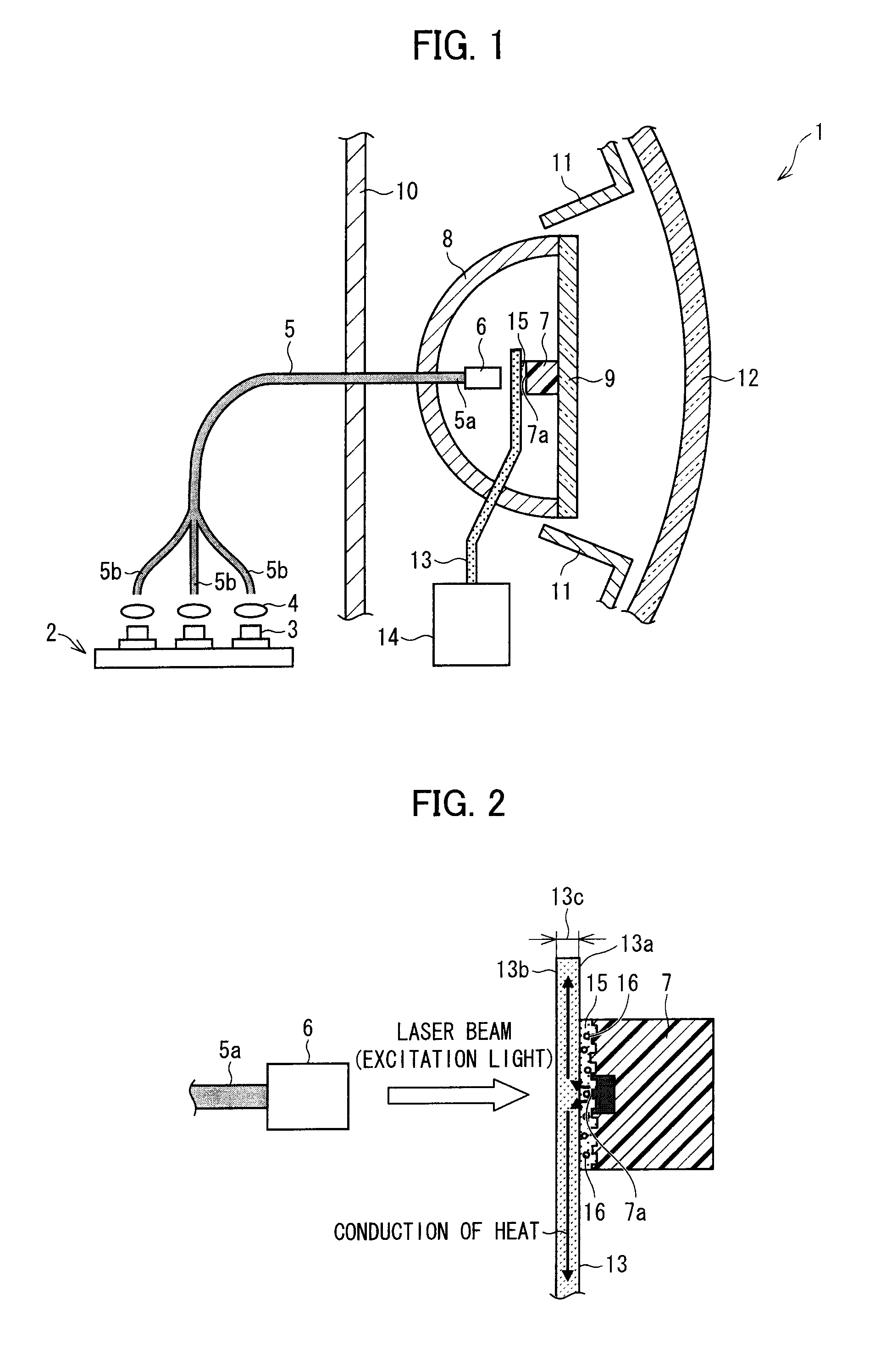
[0099]The following describes a first embodiment of the present invention with reference to FIGS. 1 through 6. In the first embodiment, a vehicle headlamp (light emitting device; illuminating device; vehicle headlamp) 1 is described as an example of an illuminating device of the present invention. The illuminating device of the present invention may, however, be in the form of (i) a headlamp for a vehicle or a moving object other than a vehicle (e.g., a human, a ship, an aircraft, a submarine, and a rocket), or (ii) other illuminating devices. The other illuminating devices encompass, for example, a searchlight, a projector, a streetlight, a traffic light, and a home illuminating device.

[0100]The headlamp 1 may comply with (i) a light distribution characteristic standard of a running headlamp (high beam) or (ii) a light distribution characteristic standard of a dipped headlamp (low beam).

[0101](Configuration of Headlamp 1)

[0102]The description below first deals with a configuration ...

Example

Example

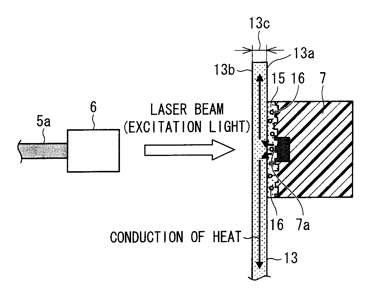
[0241]The following description deals with an Example of the present invention with reference to FIG. 6. FIG. 6 is a view illustrating specific examples of the light emitting section 7 and the heat conducting member 13.

[0242]The Example used as the light emitting section 7a wavelength conversion member including (i) a sealing material and (ii) an oxynitride fluorescent material (Caα-SiAlON:Ce) and a nitride fluorescent material dispersed in the sealing material. The light emitting section 7 had a discoid shape, and was 3 mm in diameter and 1.5 mm in thickness.

[0243]The Example used as the heat conducting member 13 a sapphire plate (thermal conductivity: 42 W / mK) having a thickness of 0.5 mm. The light emitting section 7 was adhered, as illustrated in FIG. 6, to the heat conducting member 13 by using Epixacolle EP433 (visible light polymerizable optical adhesive manufactured by Adell Corporation) as the adhesive layer 15.

[0244]A light emitting section including Caα-SiAlON:Ce a...

Example

[0250]The following describes a second embodiment of the present invention with reference to FIGS. 7 and 8. Members similar to their respective equivalents in Embodiment 1 are each assigned the same reference numeral, and are thus not described here. The present embodiment describes another example member which is used in combination with the heat conducting member 13 to sandwich the light emitting section 7.

[0251]FIG. 7 is a view schematically illustrating a configuration of a headlamp 30 of the present embodiment. As illustrated in FIG. 7, the headlamp 30 includes a transparent plate (fixing section; pressure applying mechanism; facing member) 18, a metal ring (storing member) 19, a reflecting mirror (reflecting member) 81, a substrate 82, and screws (pressure applying mechanism) 83. The light emitting section of the headlamp 30 is sandwiched between the heat conducting member 13 and the transparent plate 18.

[0252]The reflecting mirror 81 is similar in function to the reflecting m...


PUM

PropertyMeasurementUnit
Lengthaaaaaaaaaa
Lengthaaaaaaaaaa
Thicknessaaaaaaaaaa

Abstract

A headlamp disclosed includes: a laser diode for emitting a laser beam; a light emitting section including a fluorescent material which emits light in response to excitation light emitted from the laser diode; a light-transmitting heat conducting member which is provided so as to face a laser beam irradiation surface of the light emitting section and receive heat of the light emitting section; and an adhesive layer filling a gap between the heat conducting member and the laser beam irradiation surface. This arrangement improves efficiency of the heat conducting member in absorbing the heat of the light emitting section, and consequently cools the light emitting section efficiently.

Description

[0001]This Nonprovisional application claims priority under 35 U.S.C. §119(a) on (i) Patent Application No. 2010-199958 filed in Japan on Sep. 7, 2010, (ii) Patent Application No. 2010-199959 filed in Japan on Sep. 7, 2010, (iii) Patent Application No. 2010-294098 filed in Japan on Dec. 28, 2010, and (iv) Patent Application No. 2010-294100 filed in Japan on Dec. 28, 2010, the entire contents of all of which are hereby incorporated by reference.TECHNICAL FIELD[0002]The present invention relates to (i) a light emitting device functioning as a high-luminance light source and (ii) an illuminating device and a vehicle headlamp each including the light emitting device.BACKGROUND ART[0003]In recent years, studies have been intensively carried out for a light emitting device that uses, as illumination light, fluorescence emitted from a light emitting section (wavelength converting member) which includes a fluorescent material. The light emitting section emits the fluorescence upon irradiati...

Claims


Application Information

Patent Timeline
IPC IPC(8): B60Q1/04B23P11/00F21V9/16F21V9/40F21W107/10
CPCF21S48/115F21V9/16F21V29/004F21Y2101/025Y10T29/49002F21S48/321F21K9/56F21K9/90Y10T29/49826F21S48/1241F21S8/04F21V29/70F21Y2115/10F21Y2115/30F21K9/64F21S41/16F21S41/176F21S41/24F21S45/10F21S45/43F21S45/46F21S45/47F21S45/48F21S45/49F21S45/60F21S45/70F21V9/30
Inventor KISHIMOTO, KATSUHIKOKAWANISHI, HIDENORI
Owner SHARP FUKUYAMA LASER CO LTD
Why Eureka
Try Eureka