
Fluid bearing to support stent tubing during laser cutting

Active Publication Date: 2012-03-08
ABBOTT CARDIOVASCULAR
View PDF4 Cites 56 Cited by
  • Summary
  • Abstract
  • Description
  • Claims
  • Application Information

AI Technical Summary

Benefits of technology

[0005]In general terms, the present invention provides a new and improved method and apparatus for direct laser cutting stents by enabling greater precision, reliability, structural integrity and overall quality.
[0006]The present invention provides an improved system for producing stents with a fine precision structure cut from a small diameter, thin-walled, cylindrical tube. The tubes are typically made of stainless steel, other biocompatible materials, or biodegradable materials, and are fixtured under a laser and positioned utilizing a CNC machine to generate a very intricate and precise pattern. Due to the thin wall and the small geometry of the stent pattern, it is necessary to have very precise control of the laser, its power level, the focus spot size, and, importantly, the precise positioning of the laser cutting path.
[0007]In keeping with the invention, a stent tubing is held in a collet in a CNC machine so that the stent tubing is able to rotate and translate relative to a fixed laser beam. In order to support the stent tubing, a bearing or bushing supports the stent tubing just proximal to the laser beam (between the collet and the laser beam). In this manner, the stent tubing is prevented from sagging or deflecting away from the laser beam, which would otherwise create inaccuracies in the cut stent pattern. In the present invention, a fluid bearing includes a housing having a gas inlet port and a fluid inlet port on its outer surface. A bearing is positioned within the housing and the bearing has multiple blades that are aligned with the gas inlet port on the housing. The bearing is free to rotate within the housing without touching the housing. The gas inlet port is positioned to inject a high pressure gas on the blades in order to impart a high speed rotation of the bearing within the housing. The fluid inlet port on the housing is positioned to inject fluid onto an inner surface of the bearing so that as the bearing rotates at high speed, a thin film of fluid adheres to the inner surface of the bearing. The stent tubing is inserted through an inner diameter of the bearing so that the bearing supports the stent tubing just proximal of the laser beam. As the bearing rotates at high speed, on the order of about 1,000 to 10,000 rpm (or higher), the film of fluid adheres to the inner surface of the bearing so that the film of fluid is between the inner surface of the bearing and the outer surface of the stent tubing. Since the bearing is rotating at high speed and a film of fluid is formed between the inner surface of the bearing and the outer surface of the stent tubing, the stent tubing is centered within the bearing thereby creating a near frictionless environment as the stent tubing translates and rotates relative to the laser beam. The fluid film has very low friction and will not place a significant resistive load on the stent tubing as the collet or CNC system rotates and translates the stent tubing relative to the laser beam.

Problems solved by technology

Prior art bearings or bushings create a small amount of friction between the stent tubing and the bearing which can cause slight imperfections in the laser cutting process as the stent tubing is moved relative to the bearing.

Method used


Image

  • Fluid bearing to support stent tubing during laser cutting
  • Fluid bearing to support stent tubing during laser cutting
  • Fluid bearing to support stent tubing during laser cutting

Examples


Embodiment Construction

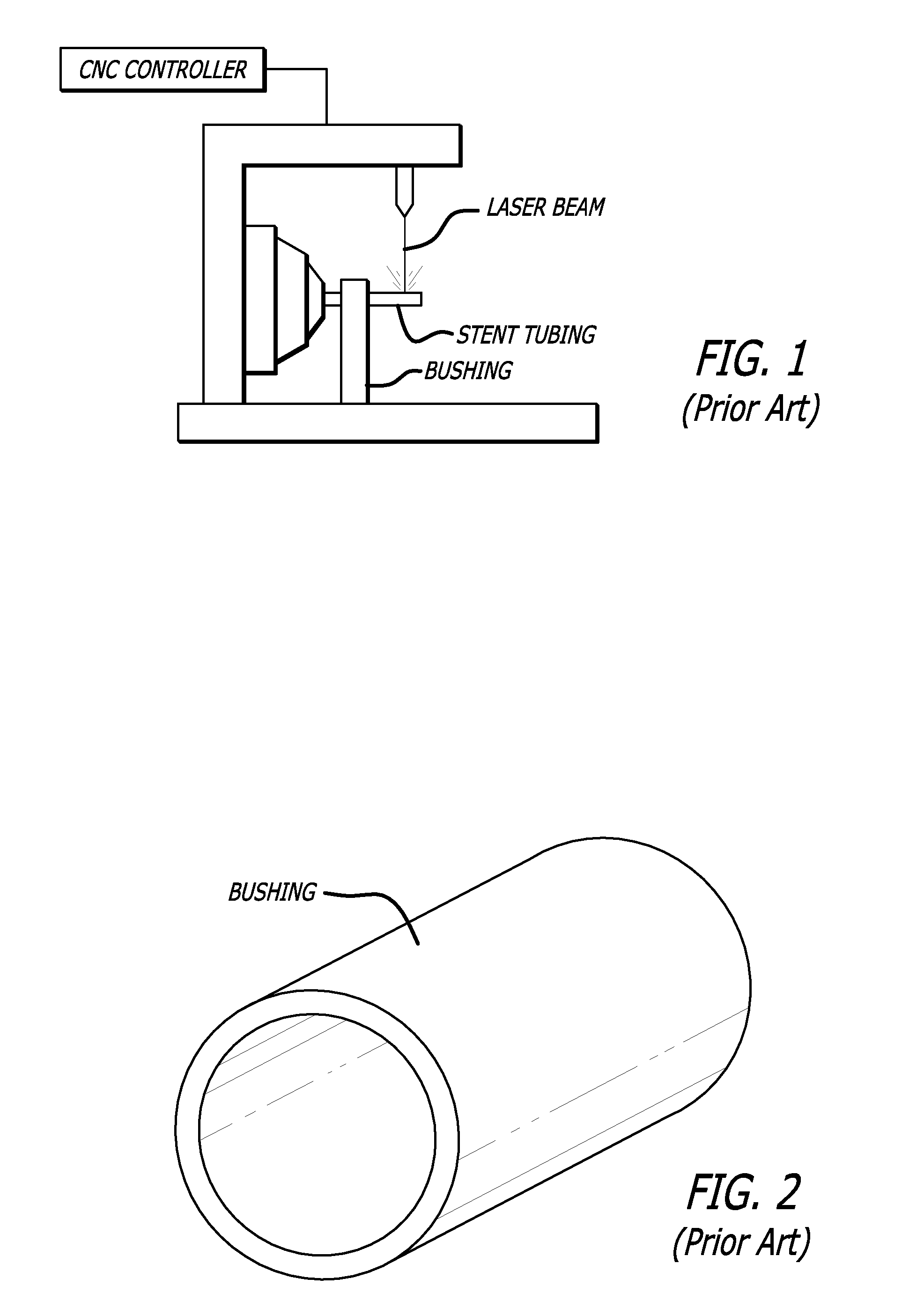
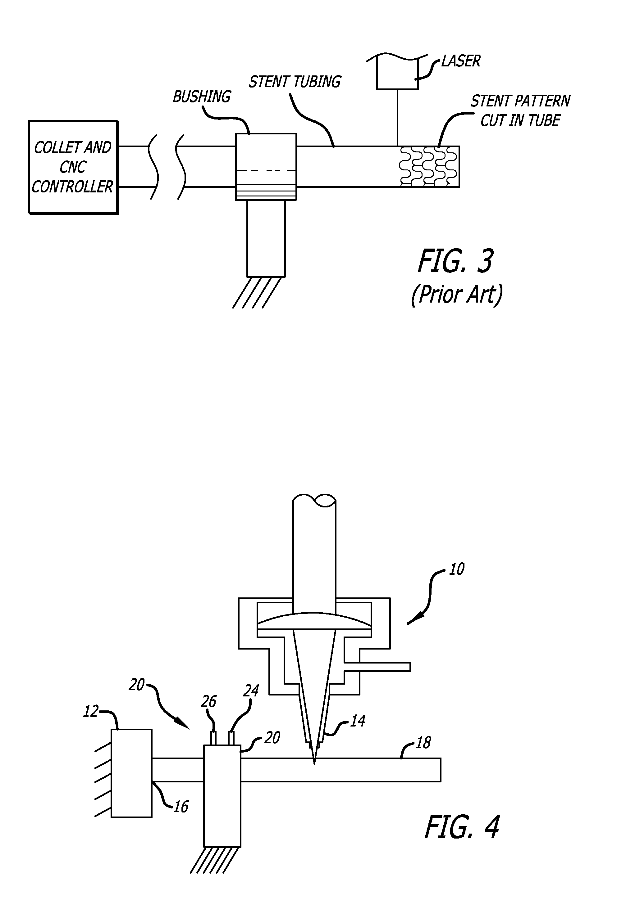
[0015]Referring to FIGS. 1-3, a typical prior art laser assembly is shown in which a laser beam is used to cut a pattern in stent tubing. The stent tubing is mounted in the collet of a CNC controller which will move the stent tubing in a translational and rotational direction while the laser beam cuts through one wall of the stent tubing to form a pattern. As shown, a bushing is used to support the stent tubing between the collet and the laser beam (or proximal to the laser beam). The prior art bushings typically support the stent tubing, however, because the inner diameter of the support bushing is closely matched to the outer diameter of the stent tubing, there is some amount of drag or friction between the bushing and the stent tubing. The control system must supply sufficient force to overcome the inertia of the tubing and the drag caused by the interface between the bushing and the stent tubing, and at the same time accurately position the stent tubing for laser cutting. It is ...


PUM

PropertyMeasurementUnit
Angular velocityaaaaaaaaaa
Pressureaaaaaaaaaa
Diameteraaaaaaaaaa

Abstract

A fluid bearing assembly provides support to stent tubing while the stent tubing is undergoing laser cutting to form a stent pattern. The fluid bearing assembly supports the stent tubing and provides a fluid barrier between the bearing and the stent tubing thereby providing nearly frictionless movement between the support bearing and the stent tubing.

Description

BACKGROUND OF THE INVENTION[0001]The invention relates generally to improvements in the manufacture of expandable stents and, more particularly, to new and improved methods and apparatus for direct laser cutting of stents in providing stents of enhanced structural quality.[0002]Stents are expandable endoprosthesis devices which are adapted to be implanted into a patient's body lumen, such as a blood vessel or coronary artery, to maintain the patency of the artery. These devices are typically used in the treatment of atherosclerotic stenosis in blood vessels, coronary arteries, and the like.[0003]In the medical arts, stents are generally tubular-shaped devices which function to hold open a segment of a blood vessel or other anatomical lumen. Stents are very high precision, relatively fragile devices and, ideally, the most desirable stents incorporate a very fine precision structure cut from a very small diameter, thin-walled cylindrical tube. In this regard, it is extremely important...

Claims


Application Information

Patent Timeline
IPC IPC(8): F16C32/06
CPCA61F2/82A61F2/91A61F2240/001B23K26/0823F16C2316/10B23Q1/38B23Q1/527F16C32/0629F16C32/0696B23K26/38F16C2322/39B23K37/053
Inventor VON OEPEN, RANDOLF
Owner ABBOTT CARDIOVASCULAR
Learn More