Imaging method

a technology of imaging method and sensor, which is applied in the field of wound imaging, can solve the problems of inability to determine absolute, inability to accurately determine absolute, and inability to achieve reliable data from imaging techniques, etc., and achieves the effect of convenient positioning of test substrates, convenient alignment of sensors, and convenient alignment of sensors

Inactive Publication Date: 2012-03-08
MOLOGIC LTD
View PDF0 Cites 15 Cited by
  • Summary
  • Abstract
  • Description
  • Claims
  • Application Information

AI Technical Summary

Benefits of technology

[0031]Optionally, the method comprises imaging a test substrate comprising a sample from a tissue wound, wherein the test substrate is received within a structure of the docking station. In this embodiment, the docking station facilitates positioning of the test substrate relative to the sensor—when the sensor is docked in the station and the test substrate is received by the docking station, the sensor is positioned to detect the intensity of reflected light from the test substrate and communicates the detected intensity of reflected light to the processor. This effectively permits combined imaging of the tissue wound and test substrate as both signals can be communicated, via the docking station, from the sensor to the processor.
[0032]Preferably, the means for receiving the test substrate structure of the docking station comprises a port or slot of defined dimensions that are suitable for receiving the test substrate. Preferably, the dimensions of the structure allow secure positioning of the test substrate in the docking station. Suitable dimensions may be identified by the person skilled in the art, depending upon the test substrate in question, which may for example be an immunoassay test strip. In some embodiments, the structure may comprise a slot for receiving the test substrate. In addition, the docking station may comprise a suitable means for docking the sensor, such as a cradle for receiving the sensor. Preferably, placement of the test substrate into the structure of the docking station facilitates alignment of the sensor with the test substrate or part thereof that provides information on the sample within or on the test substrate. For example, if the test substrate comprises two test lines, placement of the test substrate into the structure of the docking station facilitates alignment of the sensor with the two test lines, enabling the sensor to detect the intensity of reflected light each test line.
[0033]Preferably, placement of the test substrate into the structure of the docking station enables the sensor to image the test substrate and generate a signal encoding the intensity of light detected. Most preferably, the docking station facilitates the transmission of the signal derived from the sensor to the processor for subsequent processing, analysis and / or storage of the data.

Problems solved by technology

These techniques are cheap and easy to use, but they are reliant on an individual accurately defining the boundary of a wound, which can be difficult.
Furthermore, these measurements involve direct contact with the wound, which can increase the risks of infection and be painful for the patient.
Therefore it is not possible to determine the absolute colour of an image generated by such a camera because it is distorted by this compensation, and so the imaging technique does not yield reliable data.
However, the problem with this approach is that, in practice, it is difficult and expensive to carry out, especially in a clinical or domestic environment.
Some expensive digital colour cameras allow this automatic adjustment of true colour balance to be switched off.
Another problem in illuminating wounds with white light is that white light illumination is, in fact, a mixture of light of wavelengths between 400 nm and 700 nm.
Therefore an image of a wound produced under white light illumination and detected by red, green and blue sensors does not provide clean, reliable analytical data.
However, WO 98 / 22023 does not relate to the imaging of wounds (i.e. where there is a loss of the dermatological barrier function) and thus does not acknowledge the problem of producing reliable imaging data from wounds.
However, Lau et al relates to an entirely ex-vivo sensor system and does not acknowledge the problem of imaging wounds objectively.

Method used


Image

  • Imaging method
  • Imaging method
  • Imaging method

Examples


Embodiment Construction

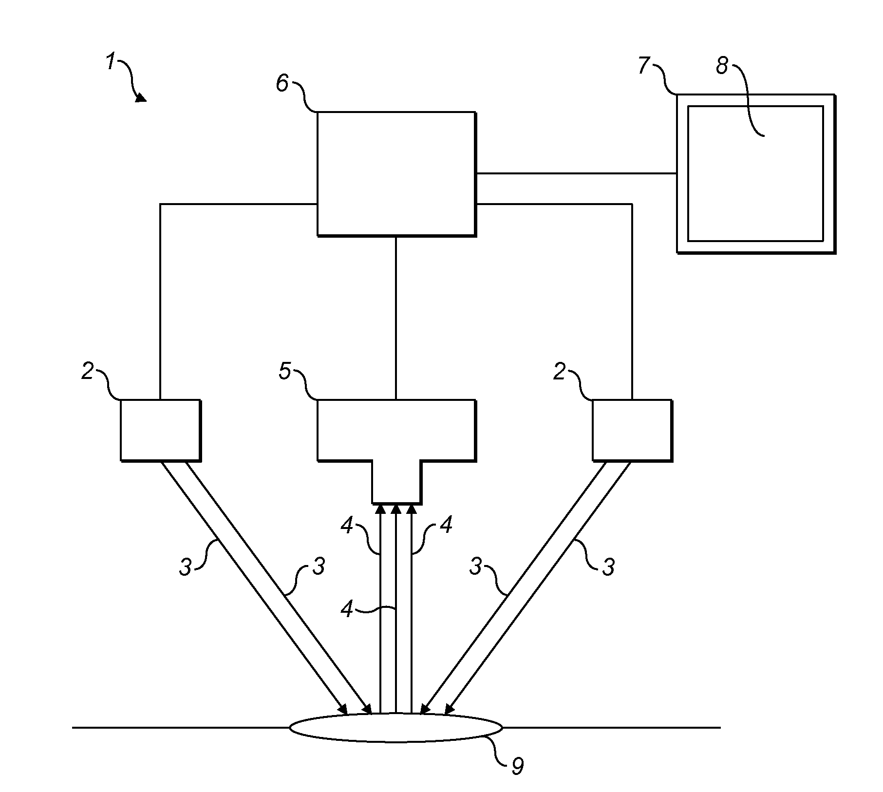
[0070]In a first embodiment of the present invention, as shown in FIG. 1, there is provided a device 1 for imaging a wound 9. The device 1 comprises first and second banks of light emitting diodes (LEDs) 2 each with a narrow band emission of 600 nm±5 nm. Located between the first and second banks of LEDs 2 there is provided a monochrome digital camera 5 which is capable of detecting light having a wavelength of between 400 nm and 1000 nm and generating a signal indicative of the intensity of the detected light. As is typical for digital cameras known in the art, the camera comprises an array of pixels, each pixel being independently sensitive to incident light and a lens arrangement for focussing incoming light on the array. The signal generated by the camera contains an indication of the intensity of the light at each pixel in the array and therefore the information necessary to generate a monochrome image of the view at which it is directed.

[0071]The first and second LED banks 2 a...


PUM


Abstract

A docking station for use in combined imaging of a tissue wound and a test substrate comprising a sample from a tissue wound, the docking station comprises means for connecting the station to a processor which processes and stores the images. The docking station also incorporates means for receiving a test substrate comprising a sample from a tissue wound. The docking station also includes means for docking a sensor in the station, which sensor detects the light reflected from an illuminated tissue wound, such that an image of the tissue wound can be communicated from the station to the processor. The means for docking is arranged such that when the sensor is docked in the station and the test substrate is received by the docking station, the sensor is positioned to detect the intensity of reflected light from the test substrate and communicates the detected intensity of reflected light to the processor to thus permit combined imaging of the tissue wound and test substrate. An apparatus for use in combined imaging of a tissue wound and a test substrate comprising a sample from a tissue wound, comprises such a docking station together with a sensor which detects the light reflected from a tissue wound and test substrate when illuminated and a test substrate for receiving a sample from a tissue wound. A method of imaging a wound comprises directing light over a wavelength range of less than 50 nm onto the wound (9). The light reflected from the wound (9) is detected with a sensor (5) that is sensitive to the intensity of the reflected light. The intensity of the reflected light is measured.

Description

FIELD OF THE INVENTION[0001]The present invention relates to wound imaging. More specifically, the invention relates to a method of imaging a wound by directing light onto the wound and corresponding devices and apparatus for performing the methods.BACKGROUND[0002]Wound diagnosis is a significant aspect of the therapeutic process. The measurement of the size of a wound is important to monitor the healing progress of the wound. Wounds that do not heal at the expected rate are identified as chronic wounds and require further treatment as soon as possible. It is common for the size of a wound to be measured using a ruler, or by tracing the outline of a wound and manually or electronically calculating the area of the tracing. These techniques are cheap and easy to use, but they are reliant on an individual accurately defining the boundary of a wound, which can be difficult. Furthermore, these measurements involve direct contact with the wound, which can increase the risks of infection a...

Claims


Application Information

Patent Timeline
Patent Type & Authority Applications(United States)
IPC IPC(8): A61B6/00A61B10/02
CPCA61B5/445A61B5/0059
Inventor DAVIS, PAUL JAMESEDWARDS, STEVE
Owner MOLOGIC LTD
Why Eureka
Try Eureka