Devices and methods for manipulating circulation in the circulatory system of a patient

Inactive Publication Date: 2012-03-08
SCHUBERT SHAI Y +1
View PDF15 Cites 39 Cited by
  • Summary
  • Abstract
  • Description
  • Claims
  • Application Information

AI Technical Summary

Benefits of technology

[0016]An increase in blood trafficking at the site of an ischemic wound can result in better mobilization of cells and molecules important for the wound healing process. Better trafficking of cells and biomolecules in the wound area may enhance the healing process resulting in improvement of non healing wounds and reduced healing time in slow healing wounds. The present invention provides a device, preferably designed as a stand alone unit, containing an adhesive flexible substrate containing a controller, a power source and one or more vibration actua

Problems solved by technology

The device results in increased blood circulation at the wound area.
The vibrations from th

Method used


Image

  • Devices and methods for manipulating circulation in the circulatory system of a patient
  • Devices and methods for manipulating circulation in the circulatory system of a patient
  • Devices and methods for manipulating circulation in the circulatory system of a patient

Examples


example 1

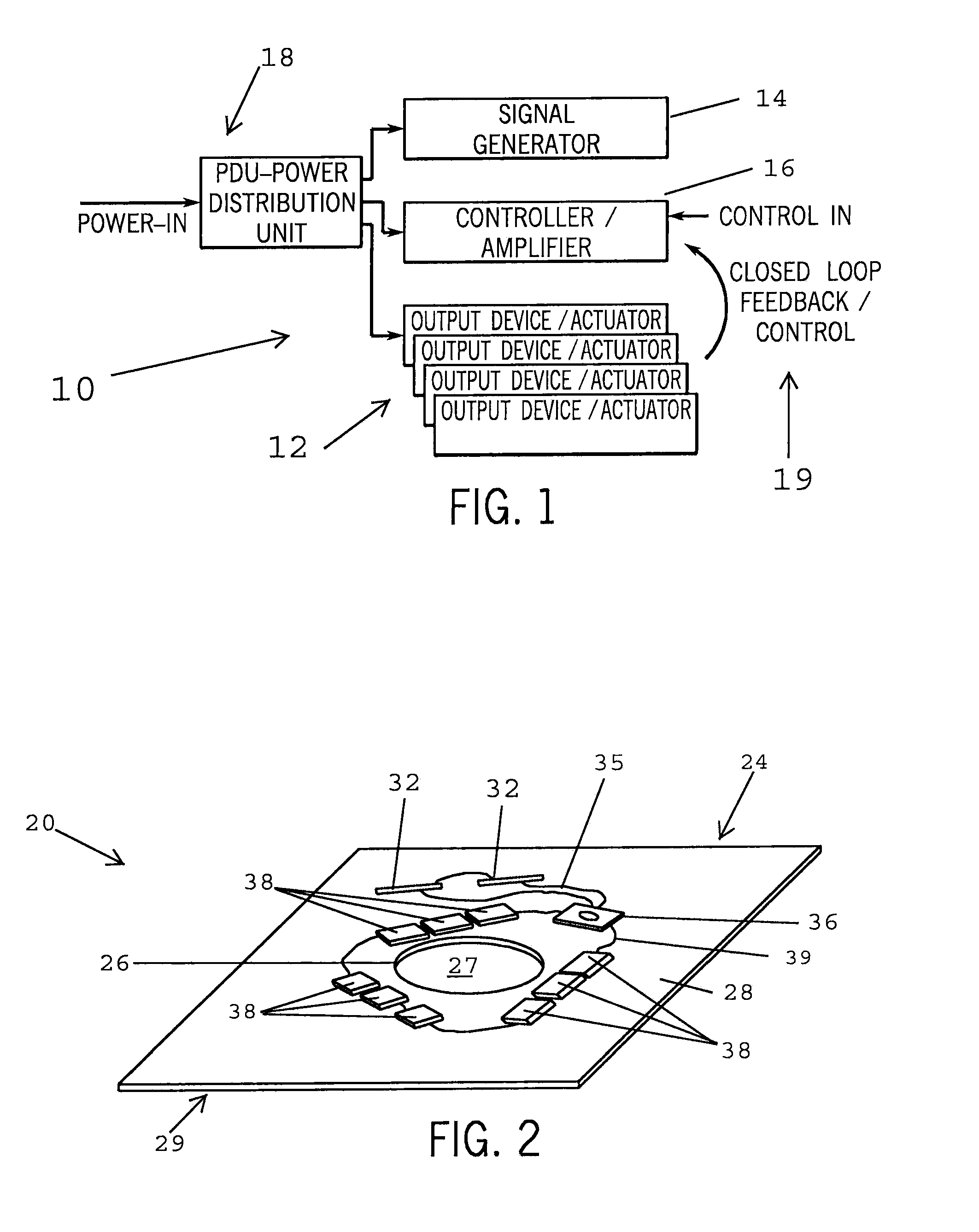
[0095]Assay method and results: A piezoelectric actuator (1 inch in diameter) was enclosed within a plastic enclosure controlled by a controller unit. The enclosure was attached to the sacrum skin of a human patient by applying adhesive tape over the actuator. After an acclimatization period of 15 to 30 minutes, vibration stimulation was started (20 Hz, 8 mils amplitude) and was continued as intermittent stimulation in 5 minute on / off cycles. THI (total hemoglobin index) was recorded versus time. After 50 minutes, the THI levels reached a plateau and the stimulation was terminated. Following a decline period and a return to baseline levels of THI, stimulation was renewed and a new cycle started at 267 minutes. The blood flow stimulation cycle can be used for the development of a continuous operation algorithm such that the device can be self regulated and increase blood flow over prolonged periods of time. For example, the plot of THI vs. time in FIG. 13 teaches that an actuator wit...

example 2

[0096]A vibration device as in Example 1 was applied to the ankle of a human patient. The device increased blood flow in the heel and toes (prime location for diabetes and arterial foot ulcers) by over two fold as measured using moorFLPI system, a full-field video frame rate blood flow imaging system which uses a laser Doppler speckle technology.

example 3

[0097]A vibration device as in Example 1 was applied to the sacrum of a human patient. The vibration device increased tissue oxygenation at the sacrum (lower back, location of 80% of pressure ulcers) by more than 2.5 fold, measured using InSpectra™ StO2 Tissue Oxygenation Monitor with the protocol similar to Example 1. See FIG. 14.


PUM

PropertyMeasurementUnit
Forceaaaaaaaaaa
Forceaaaaaaaaaa
Lengthaaaaaaaaaa

Abstract

A device for manipulating circulation in the circulatory system of the body of a subject is disclosed. The device includes a flexible support dimensioned for covering a section of the body of the subject, a vibration inducing element embedded in or attached to the support. The support includes a patch and an attachment layer on the patch. The attachment layer includes a biocompatible adhesive suitable for attaching the patch to skin on the section of the body of the subject. The vibration inducing element is positioned in or on the support such that the vibration inducing element can transmit vibrations to the skin when the patch is adhered to the skin on the section of the body of the subject.

Description

CROSS-REFERENCES TO RELATED APPLICATIONS[0001]This application claims priority from U.S. Provisional Patent Application No. 61 / 151,843 filed Feb. 12, 2009, and U.S. Provisional Patent Application No. 61 / 158,341 filed Mar. 6, 2009, and U.S. Provisional Patent Application No. 61 / 170,107 filed Apr. 17, 2009, and U.S. Provisional Patent Application No. 61 / 250,494 filed Oct. 9, 2009, and U.S. Provisional Patent Application No. 61 / 266,327 filed Dec. 3, 2009.STATEMENT REGARDING FEDERALLY SPONSORED RESEARCH[0002]Not Applicable.BACKGROUND OF THE INVENTION[0003]1. Field of the Invention[0004]This invention relates to devices and methods for manipulating circulation in the circulatory system of the body of a subject.[0005]2. Description of the Related Art[0006]Chronic lower extremity ulcers affect approximately 2.5 million to 4.5 million people in the United States. In addition to pressure ulcers, this growing clinical problem is most prominent among the elderly. Non-healing or slow healing wo...

Claims


Application Information

Patent Timeline
IPC IPC(8): A61H1/00
CPCA61F13/0203A61F2013/00174A61F2013/00523A61F2013/00646A61F13/00051A61H23/04A61H2201/165A61H2205/10A61M1/0088A61F2013/00919A61P15/10A61P17/02A61P17/14A61P25/00A61P25/06A61P9/00A61P9/10A61M1/962A61M1/918A61M1/916
Inventor SCHUBERT, SHAI Y.BRINK-DANAN, SAGL
Owner SCHUBERT SHAI Y
Why Eureka
Try Eureka