Method and apparatus for dynamic 6dof measurement

Inactive Publication Date: 2012-03-08
MADHAVAN VISWANATHAN
View PDF1 Cites 4 Cited by
  • Summary
  • Abstract
  • Description
  • Claims
  • Application Information

AI Technical Summary

Benefits of technology

[0016]The essence of the invention is to improve the fixture (nest), that holds the target of a position measuring system to an object, so as to add a well-known and highly repeatable modulation to the position of the target, with enough features to permit identification of the location and orientation of the path, and to include the movement of the object in processing the measured path of the target to measure the position and orientation of the object. For instance, this can be accomplished by locating the target on a motor driven high precision rotary bearing or using a crank-driven deflection member. During an initial calibration process, carried out with the object (commonly a rigid body on which the improved tracker is located) being stationary, the measured path of the target due to the modulation of its position by the nest, called the static target path, can be measured. The feature(s) of the object whose position and orientation are of interest can also be measured, by the same position measuring system, and their locations with respect to the static path of the target can be identified. The static target path can be analyzed to obtain parameters (for instance, the center of the circle, the axis of the circle, and the location of one or more fiducial marks such as detents or other deflections away from circularity, that can be identified by filtering the positions) that can be used to determine the transformation (translation and rotation) that relates parameters of the path to the position and orientation of the features of interest. Thereafter, continuous or continual measurements of the path can be made ov

Problems solved by technology

Measuring multiple targets is easy for some types of systems, such as iGPS and photogrammetric systems, with maybe a small penalty in data rate, but reduces the data rate substantially for systems such as laser trackers (possible when operated in absolute distance measurement (ADM) mode).
The stated accuracy of orientation measurements is not very high.
Again, the stated accuracy of orientation measurement is not high.
In addition, the complexity and cost of these systems is very high.
There are other means of tracking the position and orientation of objects (6 DOF), such as inertial trackers, but these are of low accuracy and precision to be useful for industrial metrology applications where the accuracy is often required to be better than 100 μm.
However, the jitter in encoder signal (which depends on the precision of the encoder) and other software and hardware delays between triggering and the acquisition of the points by the laser tracker (which may be uncontrollable and variable) can cause this registration between signals to be off, resulting in significant error in roll determination.
In addition, the above requirement for communication between target device and the laser tracker causes significant practical difficulties.
Cat's eyes have an acceptance angle of ±60°, but are very expensive.

Method used


Image

  • Method and apparatus for dynamic 6dof measurement
  • Method and apparatus for dynamic 6dof measurement
  • Method and apparatus for dynamic 6dof measurement

Examples


Embodiment Construction

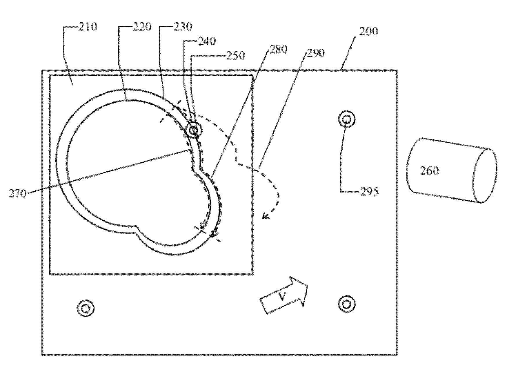
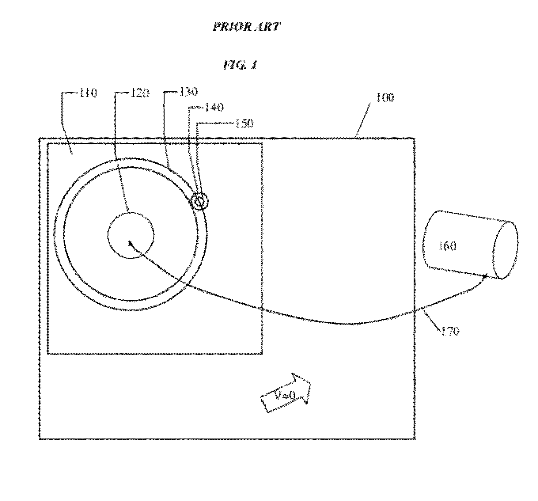
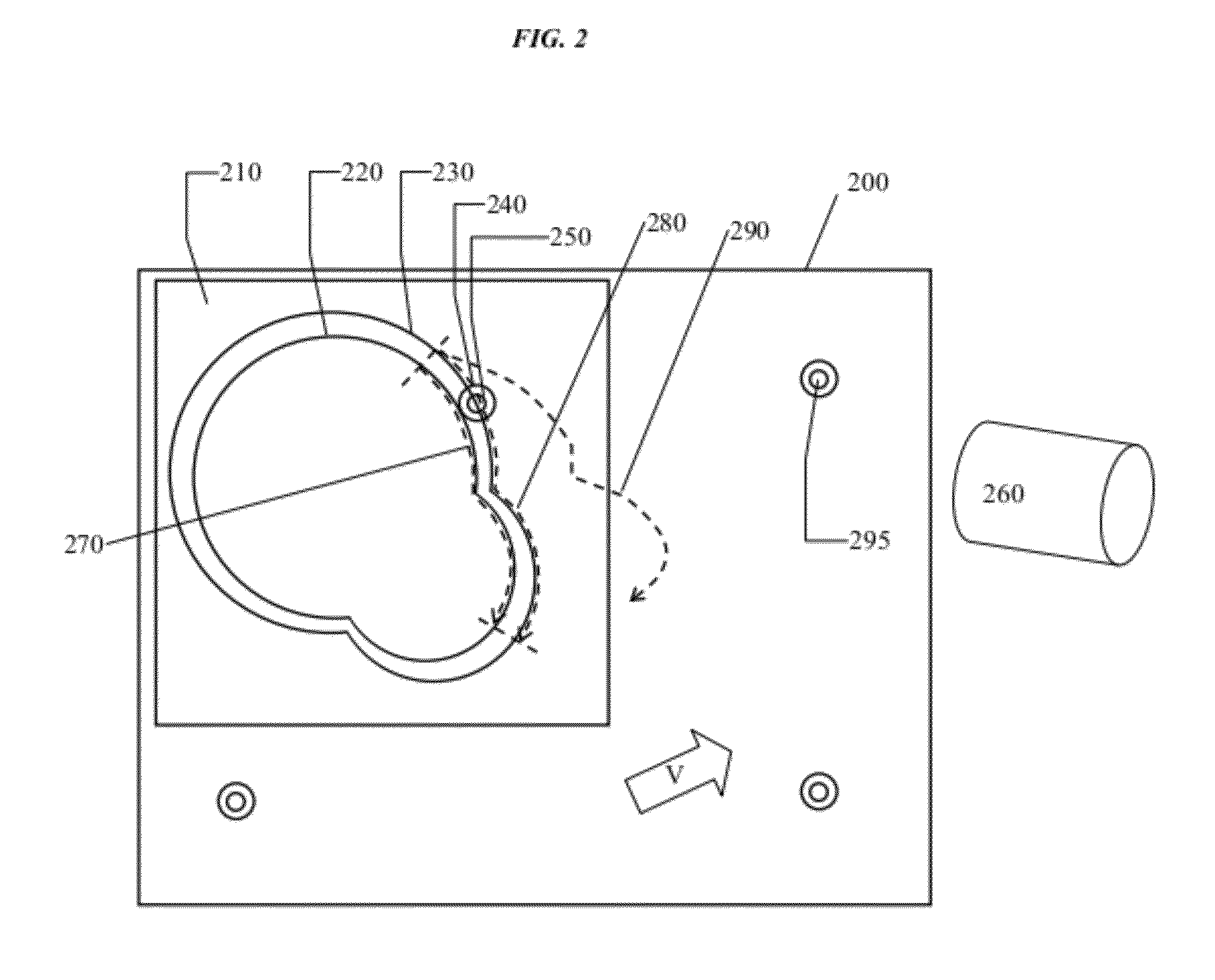
[0036]We begin by describing the most relevant prior art (Runge DE 10 2008 024 395 A1) so that the present invention and its advantages may be suitably highlighted. FIG. 1 shows a fixture 110 for moving the target 150, located on nest 140, along a known trajectory 130, using device 120. The example device 120 mentioned is a motorized bearing with an encoder attached. The position measuring device 160 (a laser tracker) measures the path of the target. By fitting a circle to the path measured 5 degrees of freedom (DOF), namely, the center of the circle and two orientations are determined. The sixth DOF is determined from encoder measurements. The encoder measurements are used to trigger the laser tracker, thereby maintaining synchronization between all 6DOF, as well as for tracking the roll of the object about the center of the bearing. As will be shown below, this method is only applicable to cases where the object is quasi-stationary. Furthermore, communication, 170, is required bet...


PUM


Abstract

A method and apparatus is disclosed that modulates the position of one target tracked by a position measuring instrument, measures the path of the target, fits the parameters of a mathematical representation of the time varying path to the path of the target measured as a function of time, and obtains the position, orientation and velocity of the object on which the apparatus is mounted. Key aspects of the modulating nest and the improved method for determining the best fit mathematical representation of the path of the target resulting from the combined effect of the modulation and the motion of the object are disclosed.

Description

CROSS-REFERENCE TO RELATED APPLICATIONS[0001]The present patent application claims benefit and priority to U.S. Prov. Pat. Appl. No. 61 / 311,302 (EFS ID 7156096) entitled “METHOD AND APPARATUS FOR DETERMINING THE POSITION AND ORIENTATION OF RIGID BODIES USING POSITION MEASURING INSTRUMENTS” and filed on Mar. 6, 2010 which is hereby incorporated by reference into the present disclosure.BACKGROUND OF THE INVENTION[0002]1. Technical Field[0003]The subject matter includes a method and apparatus for modulating the position of targets used by position measuring instruments such as laser trackers, to result in a modulating nest for tracker targets, that when mounted on an object enables accurate measurement of the position and orientation of the object as well as its velocity. This is accomplished without necessarily requiring communication between the improved target and the measurement system, which permits the improved nest to be used with all tracker systems. Additional utility of the i...

Claims


Application Information

Patent Timeline
IPC IPC(8): G06F15/00
CPCG01B11/007G01C9/00G01S17/66
Inventor MADHAVAN, VISWANATHAN
Owner MADHAVAN VISWANATHAN
Why Eureka
Try Eureka