
Depth-of-interaction scintillation detectors

Inactive Publication Date: 2012-03-15
ZECOTEK IMAGING SYST PTE
View PDF3 Cites 21 Cited by
  • Summary
  • Abstract
  • Description
  • Claims
  • Application Information

AI Technical Summary

Benefits of technology

[0011]The present invention is related to scintillation detectors capable of detecting the position or depth of gamma photon interactions occurring within a scintillator. One of the embodiments of this invention comprises at least one pair of conjunct scintillation crystal bars, wherein each pair of conjunct scintillation crystal bars is composed of two individual scintillation crystal bars positioned in a side-by-side configuration, and connected along their long sides and optically isolated from each other and from the ambient environment on the four long sides. The remaining

Problems solved by technology

A number of methods have been so far proposed for addition of the DOI capability, however, most of them rely on additional detector electronics, thereby requiring considerably more complicated hardware and introducing numerous other issues (for example, gamma quant absorption in the front-facing electronics and increased dead space in the detector ring).
Dual photo-detector (PD) readout scintillation blocks cannot be packed as tightly as single PD read-outs resulting in dead spaces between blocks where gamma-quanta cannot be captured.
Besides, this scheme requires twice as many PD and other electronic components (as compared to single PD read-outs) thereby increasing production costs.
Although this approach allows rough DOI indexing, which improves the resolution of PET imaging, it is inherently limited by the discrimination abilities of the detection electronics and by the choice of available scintillation materials.
Besides, it requires much longer coincidence windows, leading to more sparse number of events collected and to more false coincidence counts, which all make image reconstruction more difficult.
This design requires multiple scintillation crystals with different surface treatment and separated by different transparent, reflective, or opaque optical interfaces (incorporated into the detector element), which arguably makes this approach even more complicated than those based on dual detectors because of the very complex composition of the scintillation element.
However, a number of issues associated with detector manufacturing remain to be solved.

Method used


Image

  • Depth-of-interaction scintillation detectors
  • Depth-of-interaction scintillation detectors
  • Depth-of-interaction scintillation detectors

Examples


Embodiment Construction

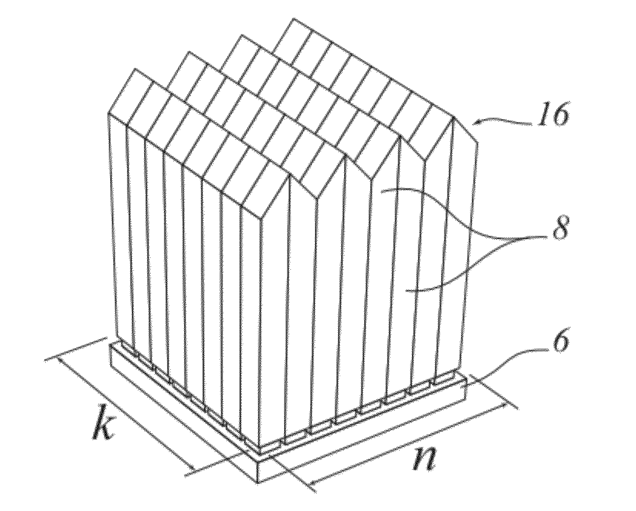
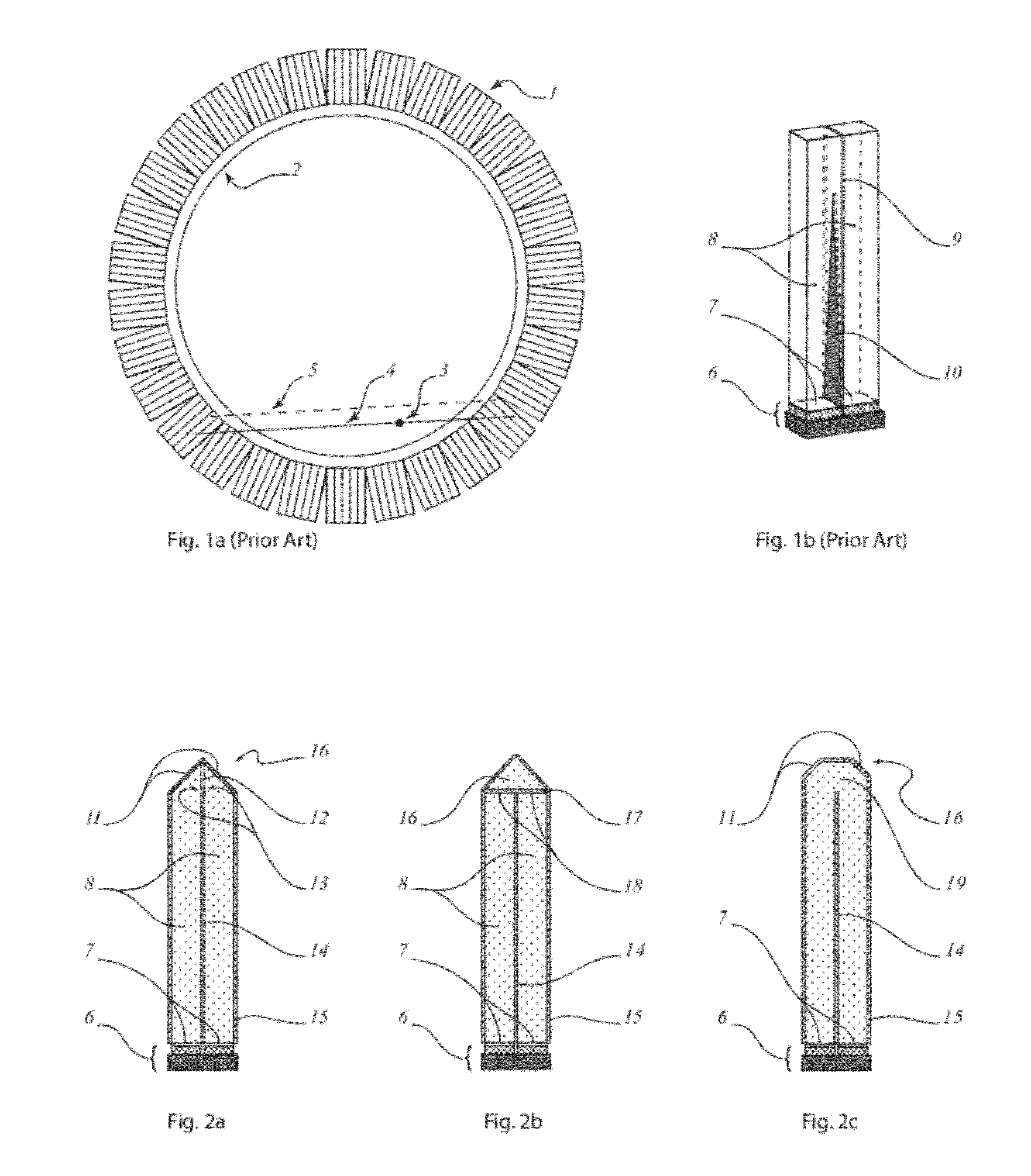
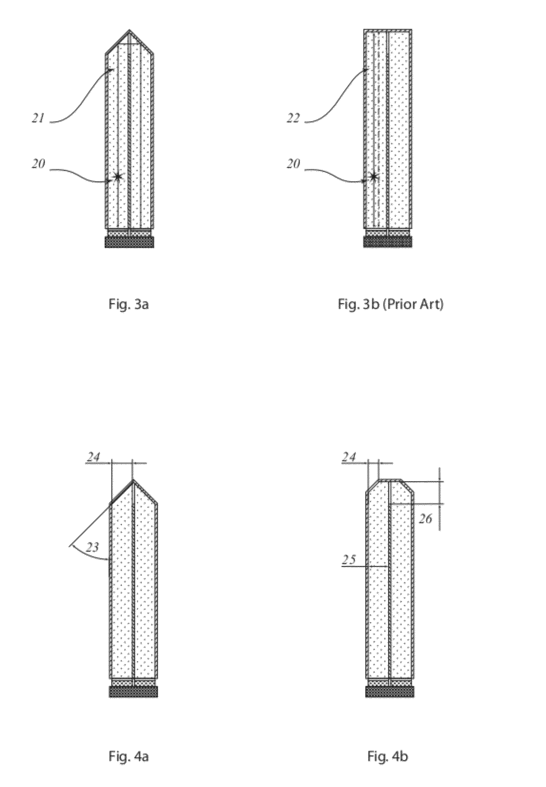
[0027]The present invention is directed to scintillation detectors capable of registering the depth coordinate of γ-photon interactions occurring within the scintillation material of the detector, thereby improving the resolution of ring-based PET imaging systems. In one embodiment and with reference to the figures (especially FIG. 2a), the present invention is directed to a scintillation detector for measuring the depth position of γ-photon interactions that comprises at least one pair of conjunct scintillation crystal elements or bars 8. Each pair of conjunct scintillation crystal bars 8 includes (i) an optical separation layer 14 positioned between two discrete scintillation crystal bars 8 for restricting light sharing between scintillation bars 8, (ii) distal coupling windows 13, one on the distal end (top portion in all Figures except FIG. 1a) of each conjunct scintillation crystal bar, which are in optical contact with each other, optionally by an intermediary of an optical in...


PUM


Abstract

The invention disclosed herein relates to a scintillation detector for registering the position of gamma photon interactions, an comprises an array of two or more elongated first and second scintillation crystal elements connected together along their respective long sides, and an array of discrete photosensitive areas disposed on a common substrate of a solid-state semiconductor photo-detector. The array of first and second scintillation crystal elements have proximal output windows optically coupled to the array of discrete photosensitive areas in a one-to-one relationship. The invention may be characterized in that the first and second scintillation crystal elements include a rooftop portion at their distal ends, wherein the rooftop portion optically couples one of the first and second scintillation crystal elements to the other and is configured to reflect and transmit light resulting from a gamma photon interaction from one of the first and second scintillation crystal elements to the other.

Description

CROSS-REFERENCE TO RELATED APPLICATIONS[0001]This application claims the benefit of priority to U.S. Provisional Application No. 61 / 382,632 and U.S. Provisional Application No. 61 / 382,636, both filed on Sep. 14, 2010. Both priority applications are incorporated herein by reference in their entireties for all purposes.TECHNICAL FIELD[0002]The invention pertains to the field of imaging gamma ray detectors such as Positron Emission Tomography (PET) and, in particular, to scintillation detectors for registering not only the transverse coordinates of gamma quanta interactions within the crystalline material of the scintillator elements of the detector, but also their depth within individual scintillator elements (commonly referred to as Depth of Interaction (DOI)), which leads to improvement in spatial resolution of PET (or any other) imaging systems based on ring detector positions, especially at the periphery of the system's field of view.BACKGROUND OF THE INVENTION[0003]Positron emiss...

Claims


Application Information

Patent Timeline
IPC IPC(8): G01T1/202
CPCG01T1/2002G01T1/202G01T1/2018G01T1/20183G01T1/20187
Inventor OLEINIK, ALEXEIZAGUMENNYI, ALEXANDERKHOREV, SERGEZERROUK, ABDELMOUNAIME FAOUZI
Owner ZECOTEK IMAGING SYST PTE
Learn More