Cortical Bone Spacers for Arthrodesis

Inactive Publication Date: 2012-03-15
SCHULMAN DANIEL
View PDF4 Cites 17 Cited by
  • Summary
  • Abstract
  • Description
  • Claims
  • Application Information

AI Technical Summary

Benefits of technology

[0010]A surgical system includes one or more spacers and methods of implanting each spacer to repair damaged living bone near a bone joint, where at least about 0.4 cm of bone length must be removed. Particularly, the spacers are adapted for restoring the original length of the bone, and preferably also the original shape. A spacer has a base and a stem. The base is shaped like the proximal or distal end of the bone to be repaired. Particularly, the base has a contact surface that is concave or convex, depending on the shape that the bone should have to complete the joint. The height of the base corresponds to the length of bone that was lost due to bone damage. The base may have pin apertures through which one or more pins may be inserted to secure the spacer to the bone. The stem is attached to or integral with the base and cooperates with a guide hole in the bone to align and attach the spacer to the bone. The base and stem may be cannulated to accommodate a K-wire or other fixation device. One or both of the base and stem may be fenestrated to increase the o

Problems solved by technology

Similarly, an arthrodesis may fail, such as when force is applied to the surgical site before the bones have ossified.
Some such failures leave dead or irreparable bone tissue at the site.
Unfortunately, the removal of dead bone tissue surrounding the joint in advance of a corrective arthrodesis may cause instability, deformity, or both, due to loss of bone length.
These problems are exacerbated in the foot, where the bones are naturally short.
This loss of length can affect the weight-bearing capabilities of the toes, resulting in an unstable gait and other balance problems, and may further be uncomfortable or aesthetically displeasing to the patient.
Unf

Method used


Image

  • Cortical Bone Spacers for Arthrodesis
  • Cortical Bone Spacers for Arthrodesis
  • Cortical Bone Spacers for Arthrodesis

Examples


Embodiment Construction

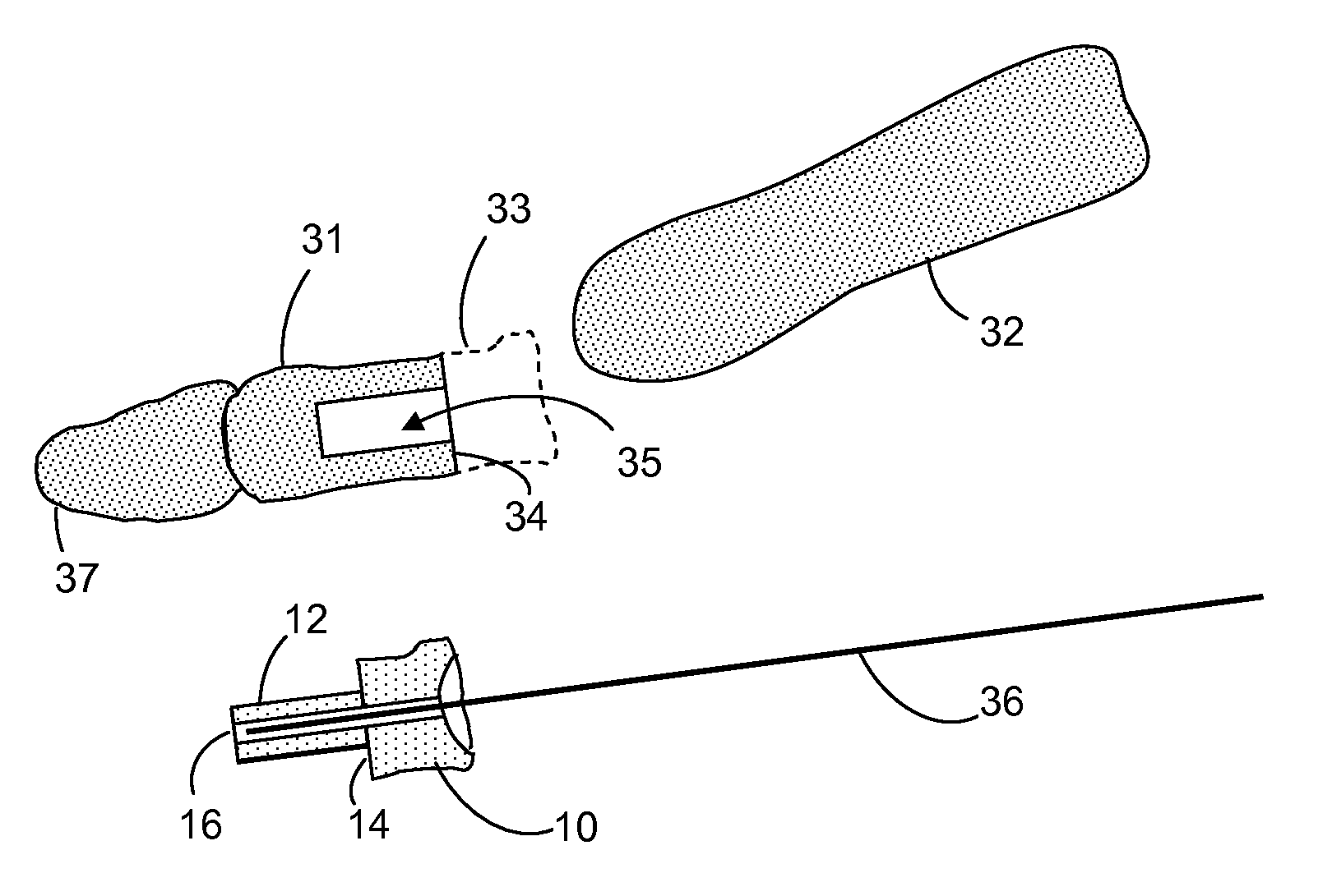
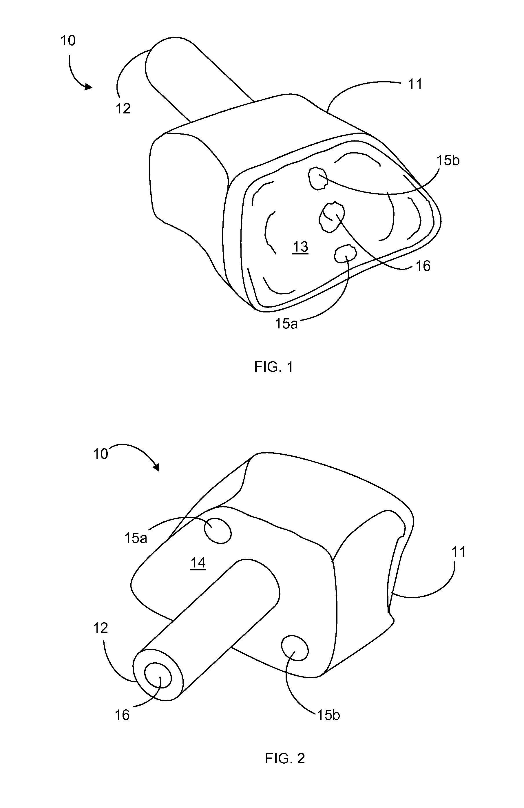
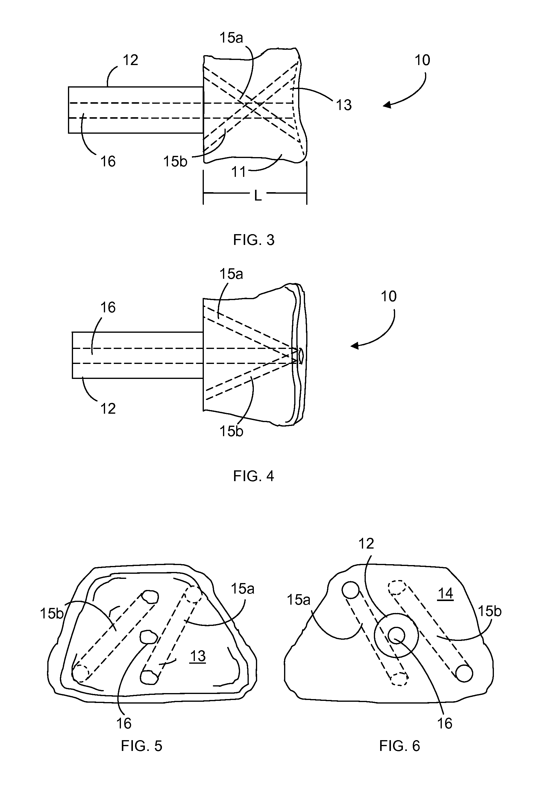
[0026]The present inventive surgical system includes one or more bone spacers for use in arthrodesis of bones across a joint, and methods of using the spacer to perform an arthrodesis. A spacer in the present system may be inserted in the proximal or distal end of either bone that forms the joint, as described herein, and is designed to replace a segment of the bone into which it is inserted, referred to herein as the “receiving bone.” The end of the receiving bone from which the bone segment is removed, which is also the end of the receiving bone that forms part of the joint, is referred to herein as the “damaged end.” The bone in the joint that cooperates with the receiving bone is referred to herein as the “cooperating bone.” The end of the cooperating bone that forms part of the joint is referred to as the “cooperating end.” It will be understood that the first or second bone, or both bones, of the joint may be receiving bones, and the proximal or distal end of either bone may b...


PUM


Abstract

A spacer is used in a damaged bone to provide a contact surface that complements the shape of a cooperating bone so a corrective arthrodesis may be performed across the two bones. The spacer further may restore the length and, preferably, the shape of the damaged bone, particularly when a discrete bone segment has been removed. The spacer has a base having the length and shape of the removed bone segment, and a stem attached to the base for securing the spacer to the damaged bone. The spacer may have one or more fixation channels for receiving fixation devices, such as k-wires or bone pins. In a method of using the spacer, gradual osteotomies are performed on the damaged bone until bleeding bone is obtained. A stem hole is drilled to receive the stem, and the spacer is inserted and aligned with the damaged and cooperating bones.

Description

CROSS-REFERENCE TO RELATED APPLICATIONS[0001]This application is a non-provisional and claims the benefit of U.S. Provisional Pat. App. Ser. No. 61 / 383,206, filed on Sep. 15, 2010.FIELD OF INVENTION[0002]This invention relates to methods and devices for performing arthrodesis. This invention relates particularly to a surgical system that uses bone graft spacers in a corrective arthrodesis to address loss of bone stock.BACKGROUND[0003]Arthrodesis is a surgical treatment that facilitates the fusion of two bones across a joint. It may be undertaken for many reasons, including relieving chronic joint pain, repairing damaged bone or surrounding structure, realigning the big toe after a bunionectomy, or correcting a failed orthopedic procedure such as an arthroplasty. It involves denuding both bones of surface cartilage where the bones will contact an implant, inserting the implant that serves as a bridge between the bones, and fixing the bones and implant together using a fixation device...

Claims


Application Information

Patent Timeline
IPC IPC(8): A61F2/30
CPCA61B17/68A61B17/7291A61F2/4225A61F2002/30622A61F2310/00359A61F2002/30878A61F2002/30901A61F2002/4235A61F2002/30772A61F2002/4233
Inventor SCHULMAN, DANIEL
Owner SCHULMAN DANIEL
Why Eureka
Try Eureka