Integrated Circuit Leakage Power Reduction using Enhanced Gated-Q Scan Techniques

Active Publication Date: 2012-03-22
QUALCOMM INC
View PDF8 Cites 15 Cited by
  • Summary
  • Abstract
  • Description
  • Claims
  • Application Information

AI Technical Summary

Benefits of technology

[0011]Embodiments of the present disclosure reduce leakage power by determining minimal leakage states of combinational log

Problems solved by technology

These toggles cause additional toggle activity throughout the entire cone of logic.
The toggle activity consumes enormous amounts of power which can detrimentally affecting the correct operation of the circuit during test and can decrease reliability of the circuit.
While the q-gating examples described with reference to FIG. 2 and FIG. 3 substantially reduce power that would otherwise be consumed due to propagated toggling of the combinational logic, e.g.

Method used


Image

  • Integrated Circuit Leakage Power Reduction using Enhanced Gated-Q Scan Techniques
  • Integrated Circuit Leakage Power Reduction using Enhanced Gated-Q Scan Techniques
  • Integrated Circuit Leakage Power Reduction using Enhanced Gated-Q Scan Techniques

Examples


Embodiment Construction

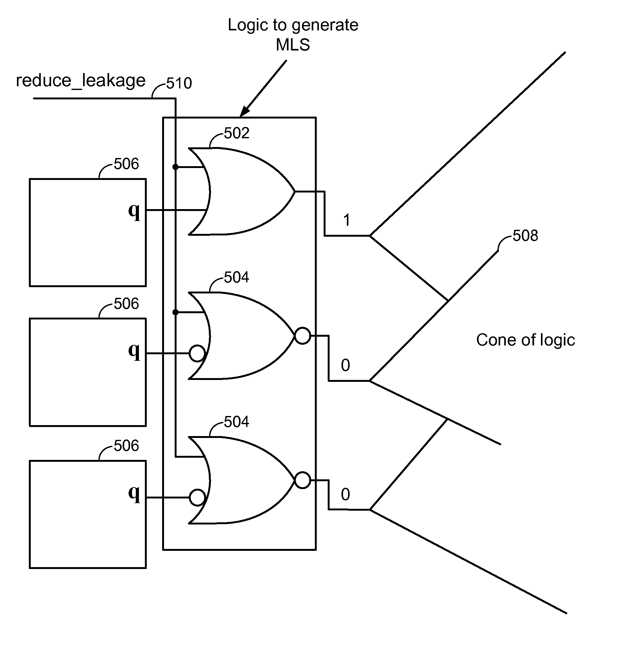
[0036]Embodiments of the present disclosure reduce leakage power by determining a reduced or minimum leakage state of combinational logic in the logic cone and parking the combinational logic in its reduced or minimum leakage state during certain modes of operation. A q-gating cell including additional hardware is inserted to gate the scan flip-flops q-output and park the logic cones in their minimal leakage state. The q-gating cell is controlled such that leakage power is reduced during several circuit modes such as: functional sleep mode; shift mode; capture mode and other test mode operations, for example. Although the term “minimum” is used throughout this application, it is understood that reduced or minimum is intended to be covered.

[0037]According to aspects of the present disclosure, hardware overhead can be limited within a user defined hardware overhead budget. By inserting the gating-logic only at the output of flops that do not lie in timing critical paths, timing of the...


PUM


Abstract

Specific logic gates for q-gating are selected by determining the minimum leakage state for a circuit design and then selecting logic gates that hold the circuit design in its lowest leakage state. Depending on the input desired to implement the minimum leakage state, the gate may be selected as a NOR or OR gate. Q-gating that is implemented with gates chosen to implement the minimum leakage state may be enabled during selected operating modes. The minimum leakage state of a circuit can be determined with an automatic test pattern generation (ATPG) tool.

Description

TECHNICAL FIELD[0001]The present disclosure generally relates to integrated circuit design. More specifically, the present disclosure relates to designing integrated circuits having a reduced leakage power.BACKGROUND[0002]Integrated circuits (ICs) are commonly designed using design-for-test techniques such as scan-based design in which scan flip flops are included in the IC designs to facilitate test mode operations of the IC. Scan flip flops are similar to standard flip flops but include a scan input, a scan output and an enable input. The enable input toggles the scan flip flop between operating mode and testing mode. When the enable input is asserted, the scan flip flops function in scan mode in which test inputs and test outputs can be transmitted via the scan input and scan output. When the enable input is deasserted, the scan flip flop operates as a standard flip flop in which input is received via the data input.[0003]In scan based design, registers in the design are converte...

Claims


Application Information

Patent Timeline
IPC IPC(8): H03K19/173
CPCG01R31/318342G01R31/318575H03K19/173H03K19/0008G06F17/50G01R31/3008G01R31/31701G01R31/3177G01R31/3183G01R31/318583H03K19/20G06F30/00
Inventor SETHURAM, RAJAMANIARABI, KARIM
Owner QUALCOMM INC
Why Eureka
Try Eureka