Honeycomb filter

a technology of honeycomb and filter, applied in the field of honeycomb filter, can solve the problems of increasing the amount of pm deposit in the downstream region, temperature rise, etc., and achieve the effect of facilitating the removal of trapped solid components and increasing the mechanical strength of the honeycomb filter

Active Publication Date: 2012-03-22
NGK INSULATORS LTD
View PDF3 Cites 31 Cited by
  • Summary
  • Abstract
  • Description
  • Claims
  • Application Information

AI Technical Summary

Benefits of technology

[0008]In honeycomb filters according to Patent Documents 1 to 3, the capacity to trap PM is improved by forming a particular layer on the partition. The particular layer has a smaller average pore size than the partition. However, this increases the permeation resistance of the partition and accordingly increases PM deposition in the downstream region, often causing a temperature rise in the downstream region while PM is removed by combustion. In accordance with Patent Document 4, an exhaust gas tends to flow through the central region, and accordingly the temperature rise in the downstream region can be decreased. However, since the trapping layer in the upstream region has a large thickness, a larger amount of exhaust gas flows to the downstream region because of the Venturi effect, for example, under high flow rate conditions, possibly increasing the amount of PM deposit in the downstream region.
[0009]In view of the situations described above, it is a principal object of the present invention to provide a honeycomb filter that has an improved capacity to trap and remove solid components contained in a fluid.
[0019]In this honeycomb filter, when the partition thickness tp, the average thickness tAve, the film thickness ratio Y1 of the downstream thickness t1 to the up- and mid-stream thickness thm, the film thickness ratio Y2 of the maximum thickness tmax to the average thickness tAve of the trapping layer, and the hydraulic diameter HDin of the cell are in their respective appropriate ranges, the capacity to trap and remove solid components contained in the fluid can be improved. When these factors are within their specified ranges, it is possible to reduce the passage of solid components through the partition portion and the entry of the solid components into pores in the partition portion, reduce excessive deposition of the solid components in the downstream region of an inlet cell, and prevent uneven distribution of the solid components or clogging with the solid components. This also ensures an exhaust gas flow path and necessary heat capacity, thereby preventing the increase in pressure loss during the deposition of solid components, providing a high regeneration limit and increasing the trapping efficiency of solid components. In this honeycomb filter, the cells include open inlet cells, which have an open inlet and a sealed outlet, and open outlet cells, which have a sealed inlet and an open outlet. The open inlet cells and the open outlet cells may be adjacent to each other. The trapping layer may be formed of particle groups having an average particle size smaller than the average pore size of the partition portion.
[0021]In a honeycomb filter according to an aspect of the present invention, the trapping layer may be formed by supplying an inorganic material that is the raw material for the trapping layer to the cell using a gas as a transport medium. Thus, transportation with a gas can be utilized to relatively easily control the morphology, such as the thickness, of the trapping layer.
[0023]A honeycomb filter according to an aspect of the present invention may be formed by joining two or more honeycomb segments with a bonding layer. Each of the honeycomb segments has the partition portion and the trapping layer. Joining with the bonding layer can increase the mechanical strength of the honeycomb filter.
[0024]In a honeycomb filter according to an aspect of the present invention, at least one of the partition portion and the trapping layer may be loaded with a catalyst. The catalyst can facilitate the removal of trapped solid components by combustion.

Problems solved by technology

However, this increases the permeation resistance of the partition and accordingly increases PM deposition in the downstream region, often causing a temperature rise in the downstream region while PM is removed by combustion.
However, since the trapping layer in the upstream region has a large thickness, a larger amount of exhaust gas flows to the downstream region because of the Venturi effect, for example, under high flow rate conditions, possibly increasing the amount of PM deposit in the downstream region.

Method used


Image

  • Honeycomb filter
  • Honeycomb filter
  • Honeycomb filter

Examples


examples

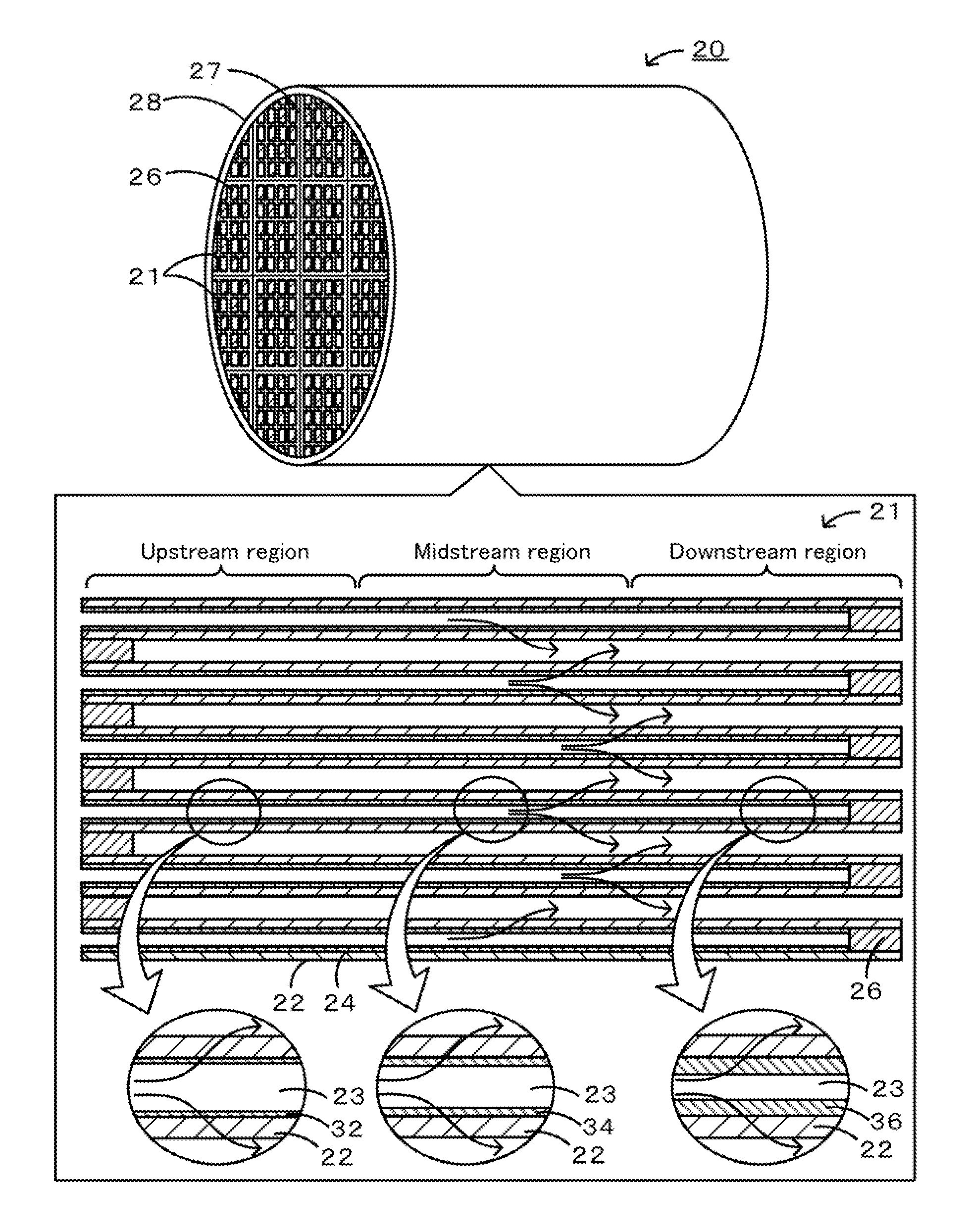
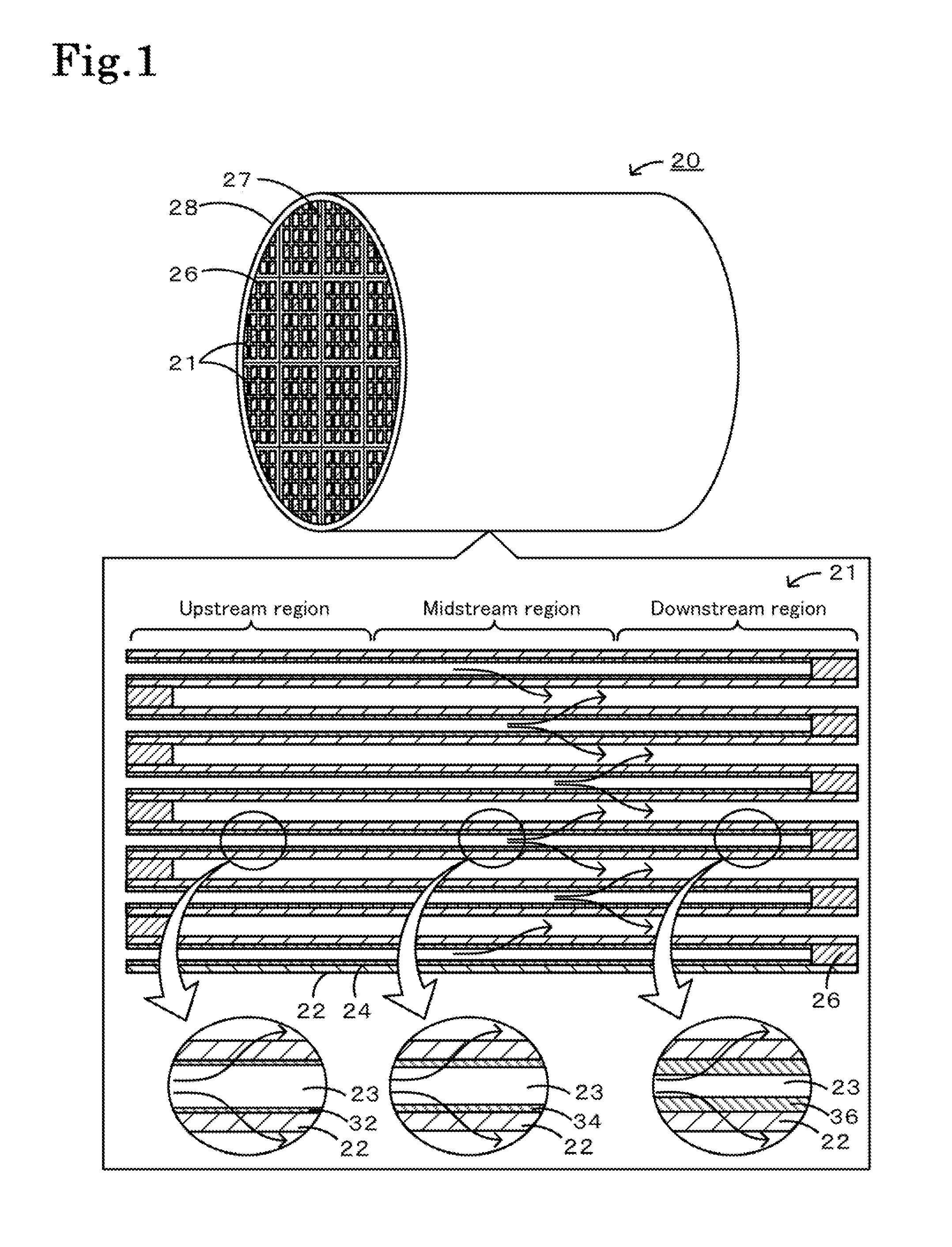
[0060]Specific examples of the manufacture of a honeycomb filter will be described below. A honeycomb filter including honeycomb segments joined together was manufactured.

[0061][Manufacture of Honeycomb Filter]

[0062]A SiC powder and a metallic Si powder were mixed at a mass ratio of 80:20. Methylcellulose, hydroxypropoxylmethylcellulose, a surfactant, and water were added to the mixture, which was then kneaded to prepare a plastic pug. The pug was extruded through a die to form a honeycomb segment formed product having a desired shape. The thickness of the partition portion was 305 μm, the cell pitch was 1.47 mm, the cross section was 35 mm×35 mm, and the length was 152 mm. The honeycomb segment formed product was dried using a microwave and then with hot air, was sealed, was calcined in an oxidizing atmosphere at 550° C. for three hours, and was baked in an inert atmosphere at 1400° C. for two hours. The sealing portions were formed by masking alternate cell openings of the segment...

examples 1 to 4

[0068]The amounts of alcohol solution and SiC particles supplied were adjusted such that the upstream thickness th was 3.7 μm, the midstream thickness tm was 3.9 μm, and the downstream thickness t1 was 7.4 μm. The resulting honeycomb filter was referred to as Example 1. In Example 1, the maximum thickness tmax was 7.6 μm, the film thickness ratio Y1 was 2.0, and the film thickness ratio Y2 was 1.6. In Examples 1 to 4 and Comparative Examples 3 to 5, the average thickness tAve was 5 μm. The amounts of alcohol solution and SiC particles supplied were adjusted such that the upstream thickness th was 1.8 μm, the midstream thickness tm was 3.1 μm, and the downstream thickness t1 was 11 μm. The resulting honeycomb filter was referred to as Example 2. In Example 2, the maximum thickness tmax was 14 μm, the film thickness ratio Y1 was 4.5, and the film thickness ratio Y2 was 2.6. The amounts of alcohol solution and SiC particles supplied were adjusted such that the upstream thickness th was...

examples 5 to 8

[0070]The amounts of alcohol solution and SiC particles supplied were adjusted such that the upstream thickness th was 14 μm, the midstream thickness tm was 18 μm, and the downstream thickness t1 was 28 μm. The resulting honeycomb filter was referred to as Example 5. In Example 5, the maximum thickness tmax was 38 μm, the film thickness ratio Y1 was 1.8, and the film thickness ratio Y2 was 1.9. In Examples 5 to 8 and Comparative Examples 6 to 8, the average thickness tmax was 20 μm. The amounts of alcohol solution and SiC particles supplied were adjusted such that the upstream thickness th was 10 μm, the midstream thickness tm was 13 μm, and the downstream thickness t1 was 38 μm. The resulting honeycomb filter was referred to as Example 6. In Example 6, the maximum thickness tmax was 45 μm, the film thickness ratio Y1 was 3.3, and the film thickness ratio Y2 was 2.2. The amounts of alcohol solution and SiC particles supplied were adjusted such that the upstream thickness th was 5.2 ...


PUM

PropertyMeasurementUnit
thickness tpaaaaaaaaaa
thickness tAveaaaaaaaaaa

Abstract

A honeycomb filter includes a partition portion having a thickness tp of 150 μm or more and 460 μm or less and a trapping layer having an average thickness tAve of 5 μm or more and 80 μm or less, wherein a film thickness ratio Y1 of a downstream thickness t1 to an up- and mid-stream thickness thm satisfies a relationship according to formula (1), wherein a film thickness ratio Y2 of the maximum thickness tmax of a trapping layer to the average thickness tAve of the trapping layer satisfies a relationship according to formula (2), and wherein a cell has a hydraulic diameter HDin satisfying a relationship according to formula (3):−4 / 375·tAve+2.05≦Y1≦−17 / 375·tAve+10.23  (1)Y2≦−1 / 15·tAve+8.33  (2); and0.95≦HDin≦2.0  (3)

Description

TECHNICAL FIELD[0001]The present invention relates to a honeycomb filter.BACKGROUND ART[0002]One proposed honeycomb filter includes a porous partition portion, in which a cell that is open at one end and closed at the other end and a cell that is closed at one end and open at the other end are alternately disposed, and a layer for trapping and removing particulate matter (hereinafter also referred to as PM) contained in an exhaust gas formed on the partition portion (see, for example, Patent Documents 1 to 3). This honeycomb filter can trap PM by the trapping layer with low pressure loss.[0003]In another proposed honeycomb filter, a trapping layer formed on a partition portion has a decreased thickness in the central region of the honeycomb filter in the exhaust gas flow direction (see, for example, Patent Document 4). In this honeycomb filter, the permeation resistance of a partition in the central region, which generally has low exhaust gas permeability, can be decreased to increa...

Claims


Application Information

Patent Timeline
Patent Type & Authority Applications(United States)
IPC IPC(8): B01D53/94B01D39/20
CPCB01D46/2474B01D53/944B01D2255/9155B01J35/04Y02T10/20F01N3/035F01N2330/60F01N2510/0682F01N3/0222Y02T10/12B01D46/2482B01D46/2478B01D46/247B01D46/2498
Inventor MIZUTANI, TAKASHINAGATA, KOJIMIYAIRI, YUKIO
Owner NGK INSULATORS LTD
Why Eureka
Try Eureka