Impact wrench

a technology of impact wrenches and hammers, which is applied in the field of impact wrenches, can solve the problems of fatigue of workers, reduced operation efficiency, numbness of hands, etc., and achieve the effects of reducing the mass of the primary hammer, increasing the length of the secondary hammer in the axial direction, and increasing the mass of the secondary hammer

Active Publication Date: 2012-03-29
KUKEN
View PDF3 Cites 15 Cited by
  • Summary
  • Abstract
  • Description
  • Claims
  • Application Information

AI Technical Summary

Benefits of technology

[0035]According to the present invention, a cylindrical secondary hammer is used, the secondary hammer rotates together with a primary hammer, and the primary hammer is housed in the internal space of the cylindrical portion of the secondary hammer. Thereby, the length of the secondary hammer in the axial direction can be increased, thus enabling the mass of the secondary hammer to be increased compared to the primary hammer. Moreover, the precession rotation is prevented by making the rotational axis of the secondary hammer coincident with the axis of the s...

Problems solved by technology

The vibrations cause fatigue to the worker and hence reduced operation efficiency ...

Method used


Image

  • Impact wrench
  • Impact wrench
  • Impact wrench

Examples


embodiment 1

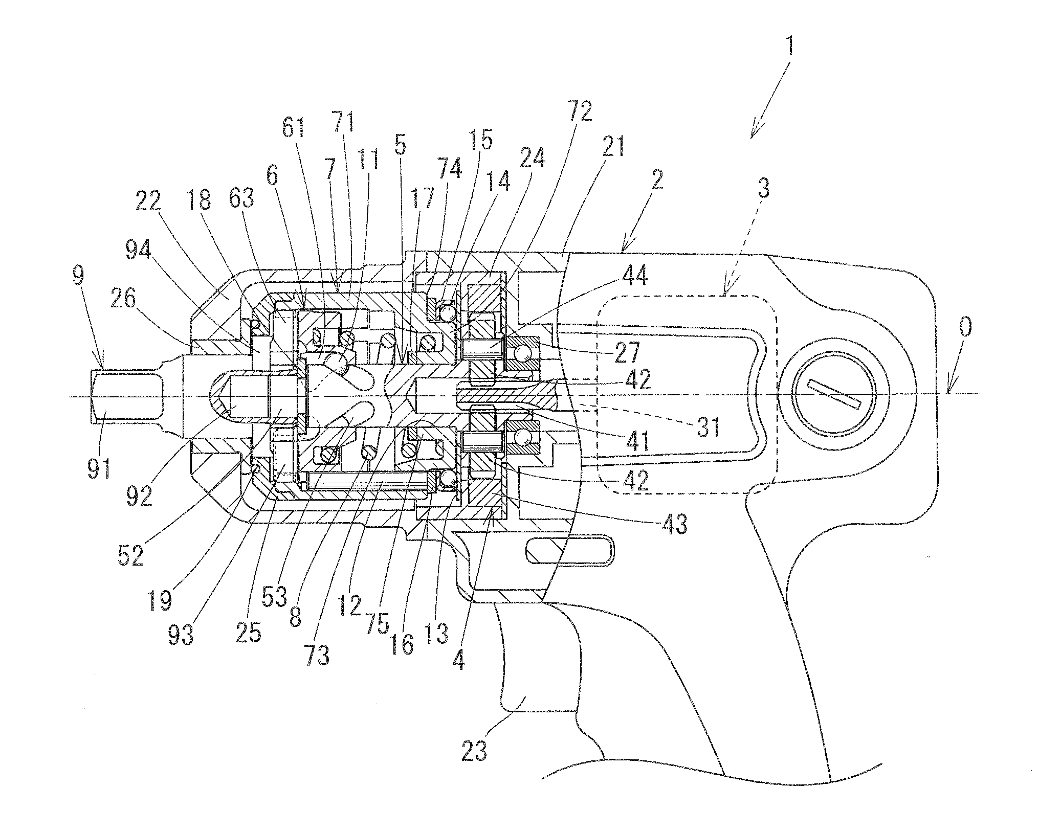
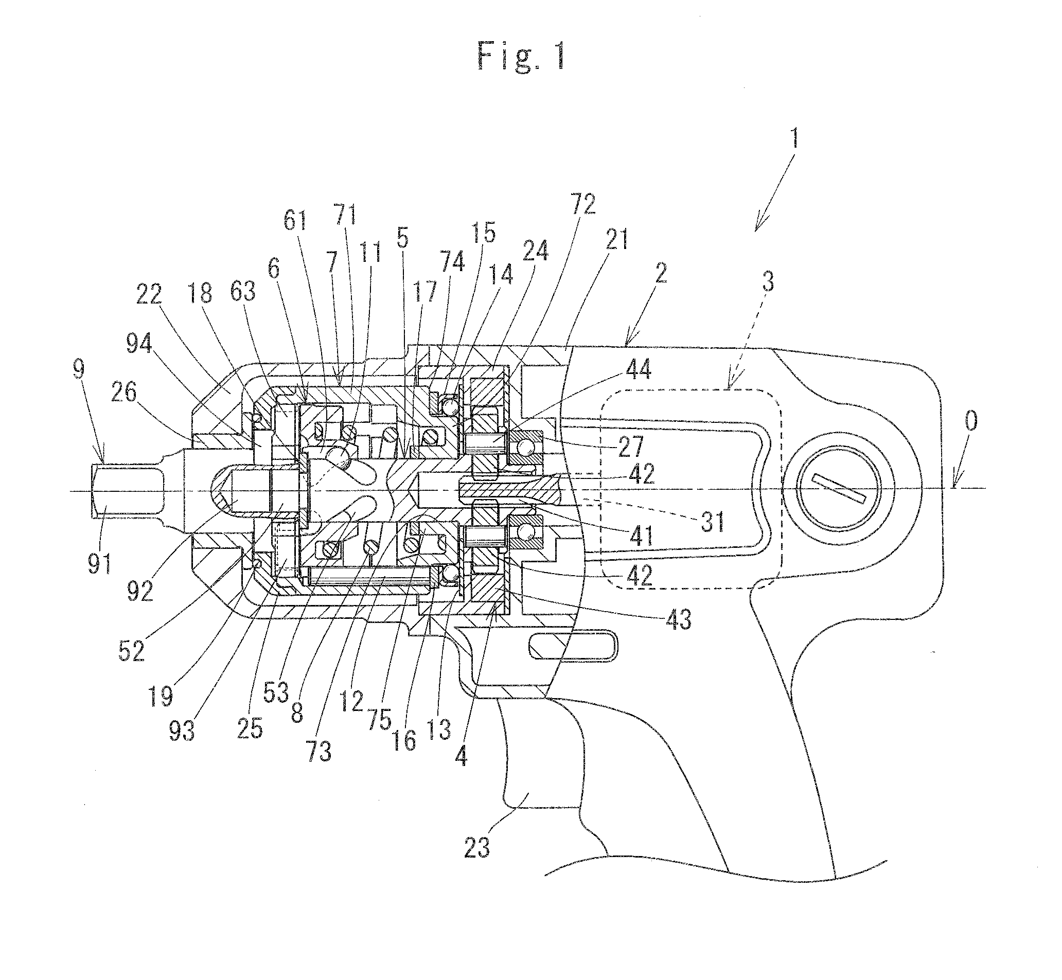
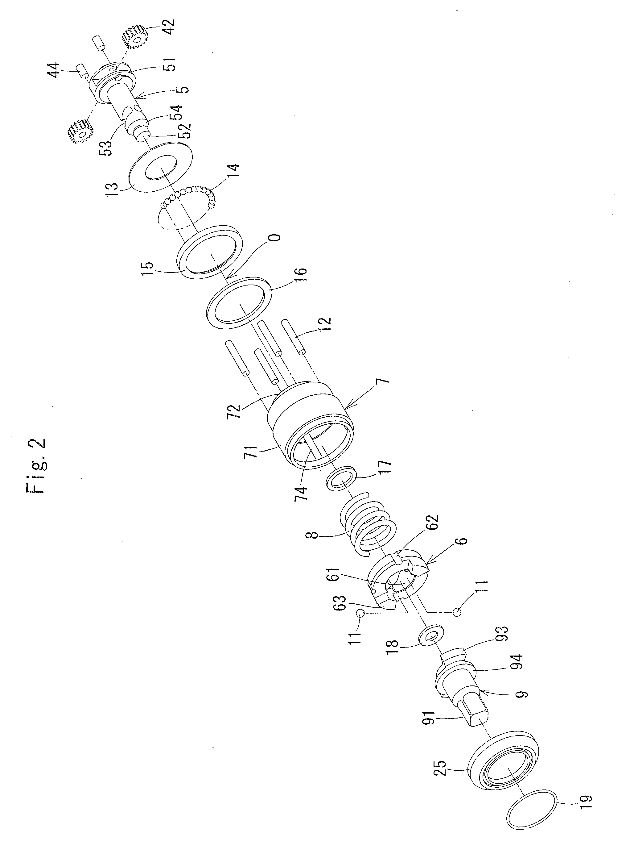
[0044]FIG. 1 is an elevation showing principal parts of an impact wrench according to Embodiment 1 of the present invention, cut in a longitudinal plane including the axis of a spindle. FIG. 2 is an exploded perspective view showing the components of the impact wrench shown in FIG. 1, excluding the case portion thereof.

[0045]

[0046]An impact wrench 1 includes a case 2, an electric motor 3, a rotation transmission mechanism 4, a spindle 5, a primary hammer 6, a secondary hammer 7, a spring 8, and an anvil 9. The structure and function of each of the components will be described below.

[0047]First, the case 2 will be described. The case 2 is composed of a resin housing 21 disposed in the rear portion of the impact wrench 1 and an aluminum clutch case 22 disposed in the front portion, and the clutch case 22 is fixed to the housing 21 by screws, which are not shown. The following description is given, taking the side where the anvil 9 is disposed as the front and the side where the electr...

embodiment 2

[0106]FIG. 5 is an elevation showing principal parts of an impact wrench according to Embodiment 2 of the present invention, cut in a longitudinal plane including the axis of a spindle. An impact wrench 1a according to Embodiment 2 is different from the impact wrench 1 according to Embodiment 1 with regard to the configuration of the axis holding means for holding the rotational axis of the secondary hammer in coincidence with the axis of the spindle. Therefore, the spindle 5, the secondary hammer 7, and the anvil 9 of Embodiment 1 are replaced by a spindle 5a, a secondary hammer 7a, and an anvil 9a.

[0107]In the following, the configuration and the operation of the impact wrench 1a will be described, focusing on the configuration of the axis holding means. Note that in FIG. 5, components having the same functions as those of the impact wrench 1 in FIG. 1 are denoted by the same reference numerals and the description thereof is omitted.

[0108]In Embodiment 1, the rotational axis of t...

embodiment 3

[0119]Although the impact wrenches 1 using the anvils 9 and 9a for tightening bolts, nuts, or the like are described in Embodiments 1 and 2 above, it is also possible to provide an impact wrench that can be used as an impact wrench for tightening machine screws such as a slotted-head screw and a cross recessed screw, with the use of an anvil having a hole formed at its tip portion for insertion of a hex bit, which is a driver bit. FIG. 6 is a cross-sectional view of the front portion of an impact wrench 1b according to Embodiment 3 of the present invention, in which an anvil 9b having a hole for insertion of a hex bit is used in place of the anvil 9 of the impact wrench 1 shown in FIG. 1.

[0120]A bit insertion hole 95 for removable attachment of a hex bit is formed at the front portion of the anvil 9b along the axis O. A steel ball 97 for engagement with a groove provided on a hex bit is inserted into an opening 96 formed in the outer circumferential face of the anvil 9b.

[0121]To in...


PUM


Abstract

An impact wrench is provided that can mitigate vibrations in the axial direction without reducing the rotary impact force of hammers. The hammers are composed of a primary hammer fitted to the outer circumference of a spindle and a cylindrical secondary hammer that is disposed so as to cover the primary hammer and that rotates integrally with the primary hammer. Furthermore, the secondary hammer is held by a center holding means in a state in which the rotational axis of the secondary hammer is coincident with the axis of the spindle in order to prevent run-out movement. With the use of the hammer configuration of the present invention, the mass of the primary hammer can be decreased compared to that of the secondary hammer, and therefore it is possible to mitigate vibrations in the axial direction while maintaining the rotary impact force.

Description

CROSS-REFERENCE TO RELATED APPLICATION[0001]This is a Continuation of PCT International Application PCT / JP2009 / 065422 filed Sep. 3, 2009, which in turn claims benefit to Japanese Patent Application No. JP 2009-0133997 filed Jun. 3, 2009, the entire disclosure of each of which is incorporated herein by reference.TECHNICAL FIELD[0002]The present invention relates to an impact wrench configured to tighten bolts, nuts, and the like firmly by applying an impact in the rotational direction.BACKGROUND ART[0003]An impact wrench is configured to tighten bolts, nuts, and the like by applying impulsive force generated by a rotationally driven hammer to an anvil serving as an output shaft. An impact wrench is provided with a motor, a spindle, a hammer, and an anvil as its main components. The operation will now be described briefly below.[0004]The motor causes the spindle to rotate at a predetermined number of revolutions, and the rotational force of the spindle is transmitted to the hammer. Ro...

Claims


Application Information

Patent Timeline
IPC IPC(8): B25B21/02
CPCB25B21/00B25B21/026
Inventor NAKAMURA, AKINORI
Owner KUKEN
Why Eureka
Try Eureka