Charge Pump

Active Publication Date: 2012-03-29
INFINEON TECH AUSTRIA AG
View PDF2 Cites 6 Cited by
  • Summary
  • Abstract
  • Description
  • Claims
  • Application Information

AI Technical Summary

Benefits of technology

[0029]The modulation of the return channel can be synchronized with the switching times of the charge pump, as this enables the times at which that of the return cha

Problems solved by technology

In general, it can be stated that the energy required increases with increasing speed and increasing demands on data integrity.
With the known methods, a bidirectional data stream cannot be transmitted via the charge pump, as the return path for data from the secondary side to the primary side is missing.
In addition, the efficiency of the charge pump is reduced due to the modulation, as it is not always possible to work with parameters which are optimum for energy transmission.
However, this has the disadvant

Method used


Image

  • Charge Pump
  • Charge Pump
  • Charge Pump

Examples


Embodiment Construction

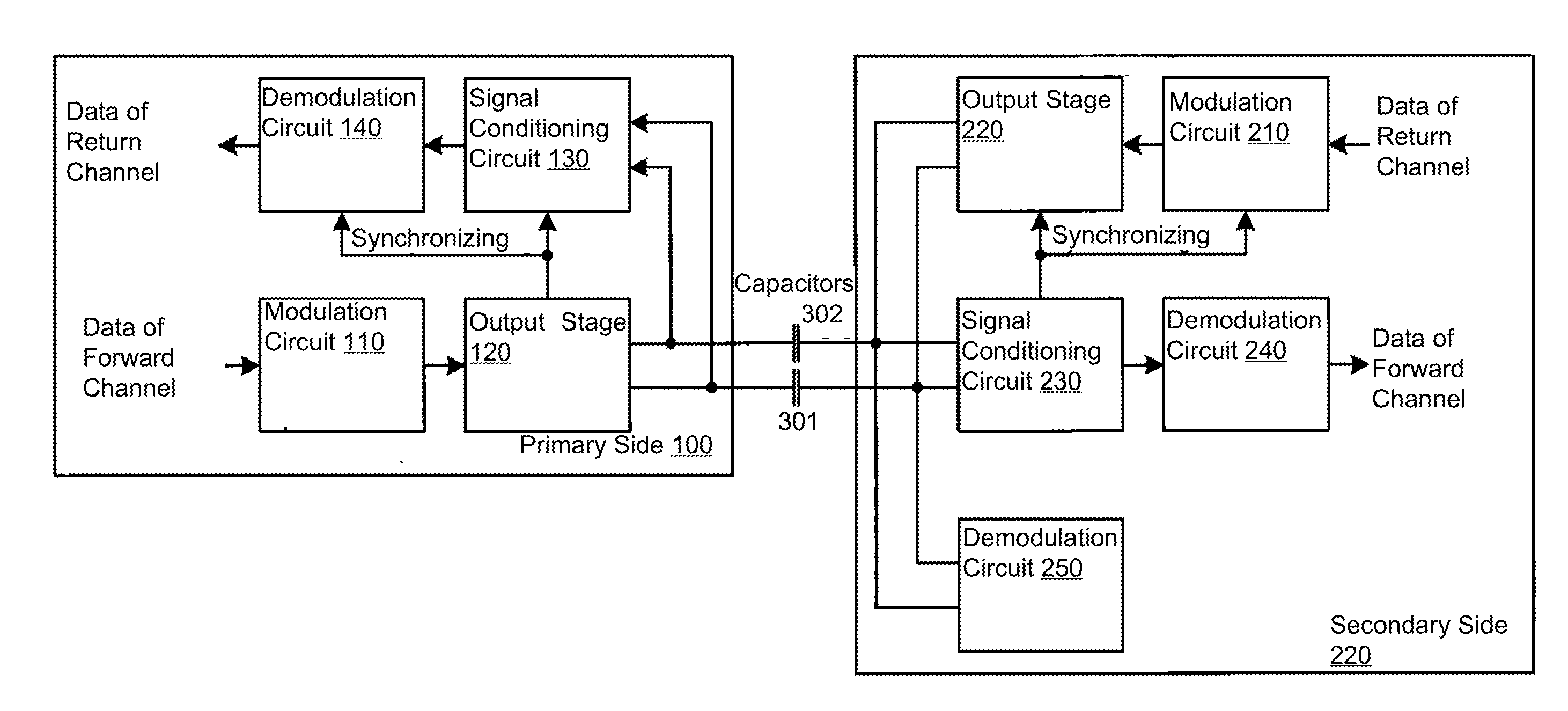
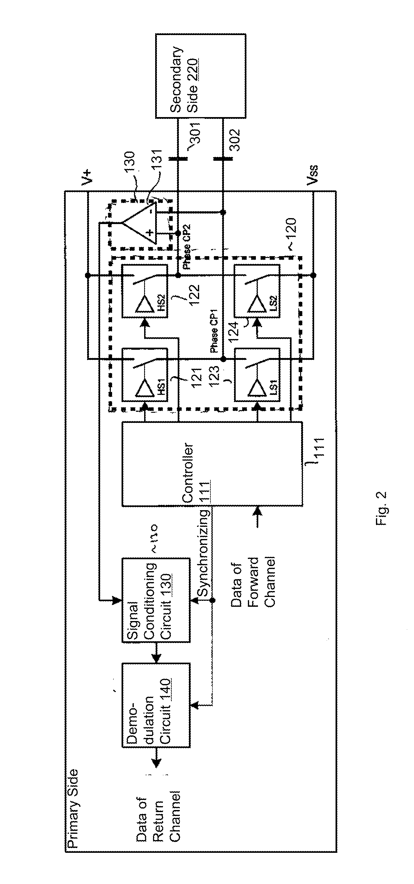
[0045]FIG. 1 shows an exemplary embodiment of a charge pump having a primary side 100, a secondary side 200 and two coupling capacitors 301, 302. The primary side 100 has a modulation circuit 110, an output stage 120, a signal conditioning circuit 130 and a demodulation circuit 140. The output stage 120 is connected to the coupling capacitors 301, 302. The output stage periodically charges the coupling capacitors 301, 302 with charge carriers. An input of the output stage 120 is connected to an output of the modulation circuit 110. The output stage 120 can be controlled by the modulation circuit 110 in such a way that the characteristics of a charge pump interval can be changed for transmitting a charge packet. The modulation circuit 110 has an input which is designed to receive transmitted data. The output stage 120 has a synchronizing output. This synchronizing output can be designed to transmit a synchronizing signal to other parts of the charge pump circuit. By way of example, a...


PUM


Abstract

A charge pump for transmitting energy and data has a primary side, a secondary side and a first coupling capacitance by way of which the primary side is connected to the secondary side, wherein the primary side is designed to periodically transmit energy in the form of a charge packet to the secondary side with the first coupling capacitance during a charge pump interval, the primary side being designed to impress an item of data on the charge pump interval by modulation, wherein the secondary side is designed to receive the item of data by demodulating the charge pump interval, wherein the secondary side is designed to impress an item of data on the charge pump interval by modulation, and wherein the primary side is designed to receive the item of data by demodulation of the charge pump interval.

Description

RELATED APPLICATIONS[0001]This Application claims priority benefit of DE Patent Application No.: 102010046964.5, filed on Sep. 29, 2010. The entire contents of the DE Patent Application No.: 102010046964.5 are hereby incorporated herein by reference.BACKGROUND[0002]The present invention relates to a charge pump for transmitting energy and data.[0003]Charge pumps have a wide area of application in electronics for providing a supply voltage. Charge pumps are used when, as well as a first supply voltage, a second supply voltage is also required, the supply voltage range of which lies at least partially outside the first supply voltage or is to be at least partially independent of the first supply voltage. These different supply voltages are referred to as voltage domains.[0004]When operating different voltage domains, energy is supplied to the individual domains by different methods, such as charge pumps or DC / DC converters for example, depending on the energy requirement of a domain.[...

Claims


Application Information

Patent Timeline
IPC IPC(8): G05F1/10
CPCH02M3/3376H04B5/0012H04B5/0093H04B5/0037H04B5/0031
Inventor BARRENSCHEEN, JENSFELDTKELLER, MARTIN
Owner INFINEON TECH AUSTRIA AG
Why Eureka
Try Eureka