Device for transforming electromagnetic ir energy from spatially incoherent, low-power density, broad-band radiation in spatially coherent, high-power density, quasi-monochromatic radiation

a technology of electromagnetic ir energy and electromagnetic field, which is applied in the field of capturing infrared electromagnetic energy, can solve the problems of increasing the intensity of cumulatively captured ac signal, limiting the sensitivity and effectiveness of em energy conversion system, and achieving large power yield

Inactive Publication Date: 2012-03-29
STMICROELECTRONICS SRL
View PDF3 Cites 1 Cited by
  • Summary
  • Abstract
  • Description
  • Claims
  • Application Information

AI Technical Summary

Benefits of technology

[0009]A device for transforming IR electromagnetic energy in form of spatially incoherent, low-power density, and broad band radiation into a spatially coherent, high-power density, and quasi-monochromatic radiation, may allow the realization of high sensitivity transducers and may make possible applications of IR electromagnetic energy conversion into electric energy with outstandingly large power yields, exploitable for energy harvesting from low enthalpy thermal wastes, for the production of electric energy from solar radiation and innumerable other useful applications.

Problems solved by technology

For such a system, it has been experimentally demonstrated that the IR electromagnetic radiation exchanged between the two bodies at different temperatures has characteristics that severely limit sensitivity and effectiveness of the EM energy conversion system of the IR radiation into an electric signal.
More realistically, the incident IR radiation is not spatially coherent and this may jeopardize the possibility of using arrays of antennas that may so increase the intensity of the cumulatively captured AC signal.

Method used


Image

  • Device for transforming electromagnetic ir energy from spatially incoherent, low-power density, broad-band radiation in spatially coherent, high-power density, quasi-monochromatic radiation
  • Device for transforming electromagnetic ir energy from spatially incoherent, low-power density, broad-band radiation in spatially coherent, high-power density, quasi-monochromatic radiation
  • Device for transforming electromagnetic ir energy from spatially incoherent, low-power density, broad-band radiation in spatially coherent, high-power density, quasi-monochromatic radiation

Examples


Embodiment Construction

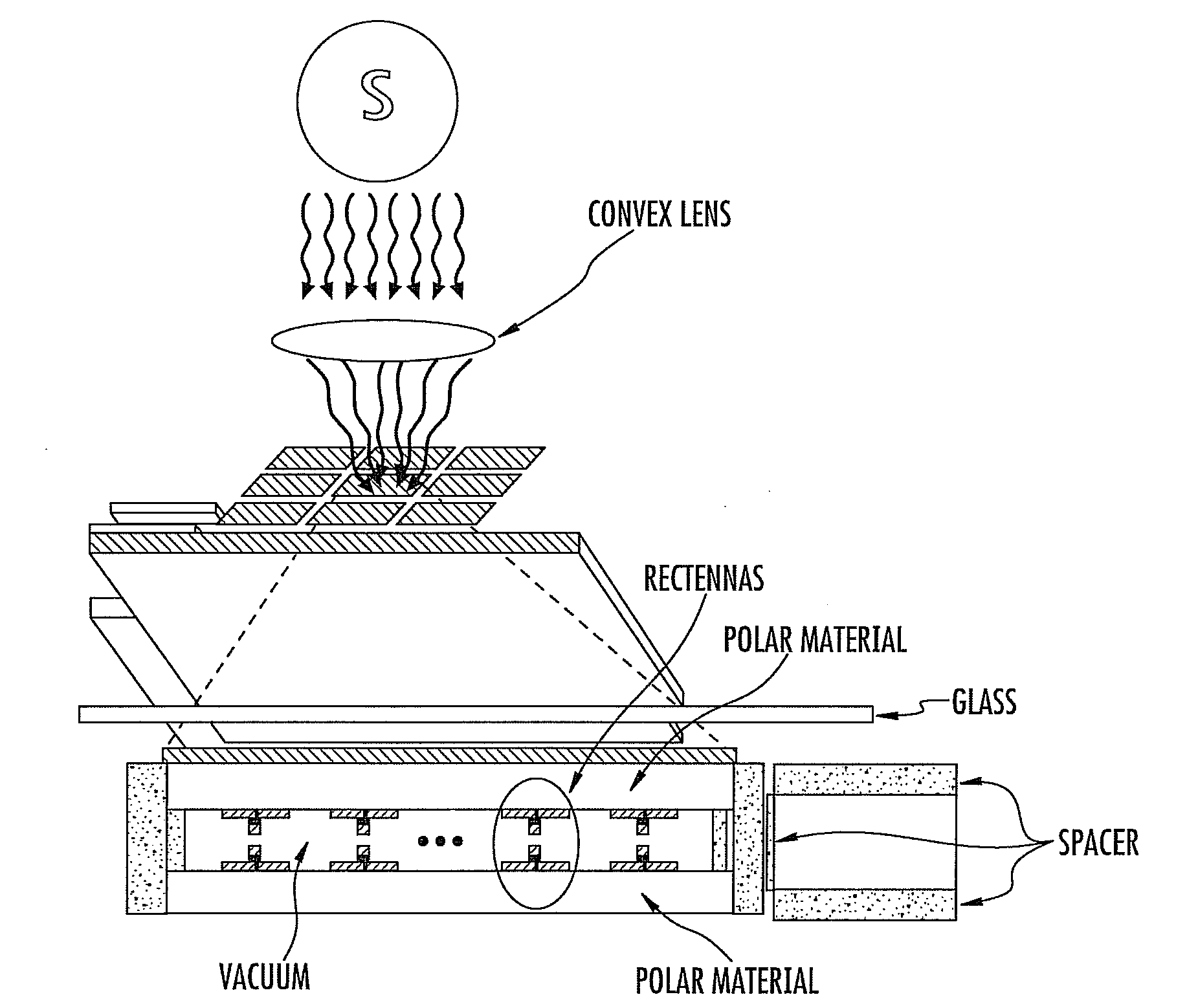
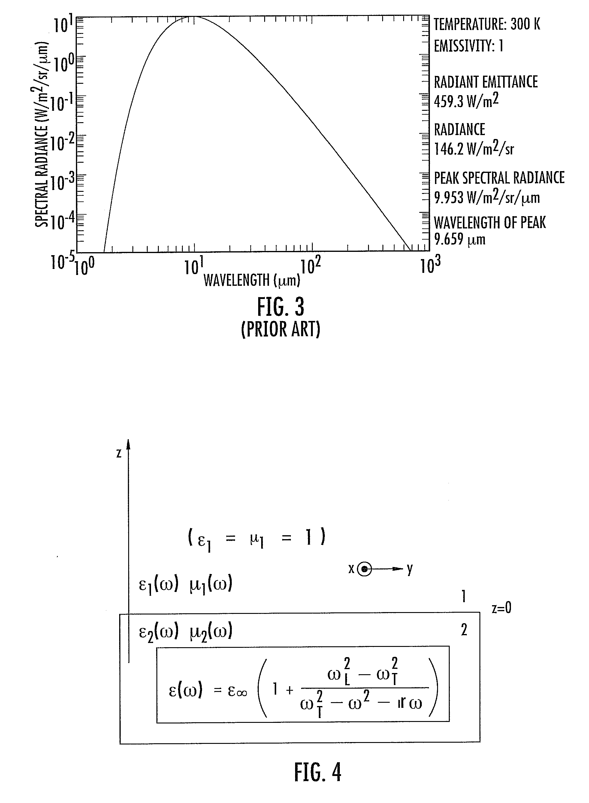
[0026]A description of this present disclosure cannot leave out of consideration the concept of superficial wave, that is known in the scientific literature. Let us consider the separation interface between two dielectric mediums, the first of which is the vacuum (1) and the second is a polar material (2) as depicted in FIG. 4. A dielectric is called polar when its so-called dielectric “constant” depends from the working frequency ω, according to the mathematical model illustrated in FIG. 4 for the second material (2).

[0027]A superficial wave is a particular approach of the Maxwell equation that is obtained for the frequencies at which the following condition is satisfied: real part of ε2(ω)=−1. This approach represents a signal that propagates along the separation surface between the two mediums (1) and (2) and that decreases exponentially in the direction perpendicular to the interface.

[0028]In this situation, the module of the wave vector K tends to infinity, as shown in FIG. 5. ...


PUM


Abstract

A device to be positioned between a heat source and a heat sink may transform infrared electromagnetic (IR-EM) energy exchanged therebetween from a first form to a second form. The device may include a pair of layers facing each other and having dielectric material with molecular excitability characteristics to produce the second form of IR-EM energy. The pair of layers may define a gap therebetween. The device may include a conversion circuit configured to convert the second form of IR-EM energy into electrical energy.

Description

FIELD OF THE INVENTION[0001]This present invention relates to capturing infrared (IR) electromagnetic energy and converting it into electric energy with power antennas matched at the working frequency to a rectifier, in particular, the matching of the impedance on the rectifier (diode) and of the complex conjugate of the impedance on the capturing antenna of the IR radiation.BACKGROUND OF THE INVENTION[0002]FIG. 1 depicts a system called a “rectenna” (rectifier+antenna), which is generally studied for application based on the superficial waves present at the interface between two media of different characteristics, at working frequencies in the order of GHz. In Mohammad Sarehraz, “Novel Rectenna for Collection of Infrared and Visible Radiation,” University of South Florida, March 2005, AC-DC power conversion yields greater than 80% have been measured for these systems at working frequencies in the range of microwaves (GHz).[0003]Rectenna systems attain such a high conversion efficie...

Claims


Application Information

Patent Timeline
IPC IPC(8): H01S3/04
CPCH02S99/00Y02E10/50
Inventor GIRLANDO, GIOVANNI
Owner STMICROELECTRONICS SRL
Why Eureka
Try Eureka