Method of shutting down fuel cell system
- Summary
- Abstract
- Description
- Claims
- Application Information
AI Technical Summary
Benefits of technology
Problems solved by technology
Method used
Image

Examples
first embodiment
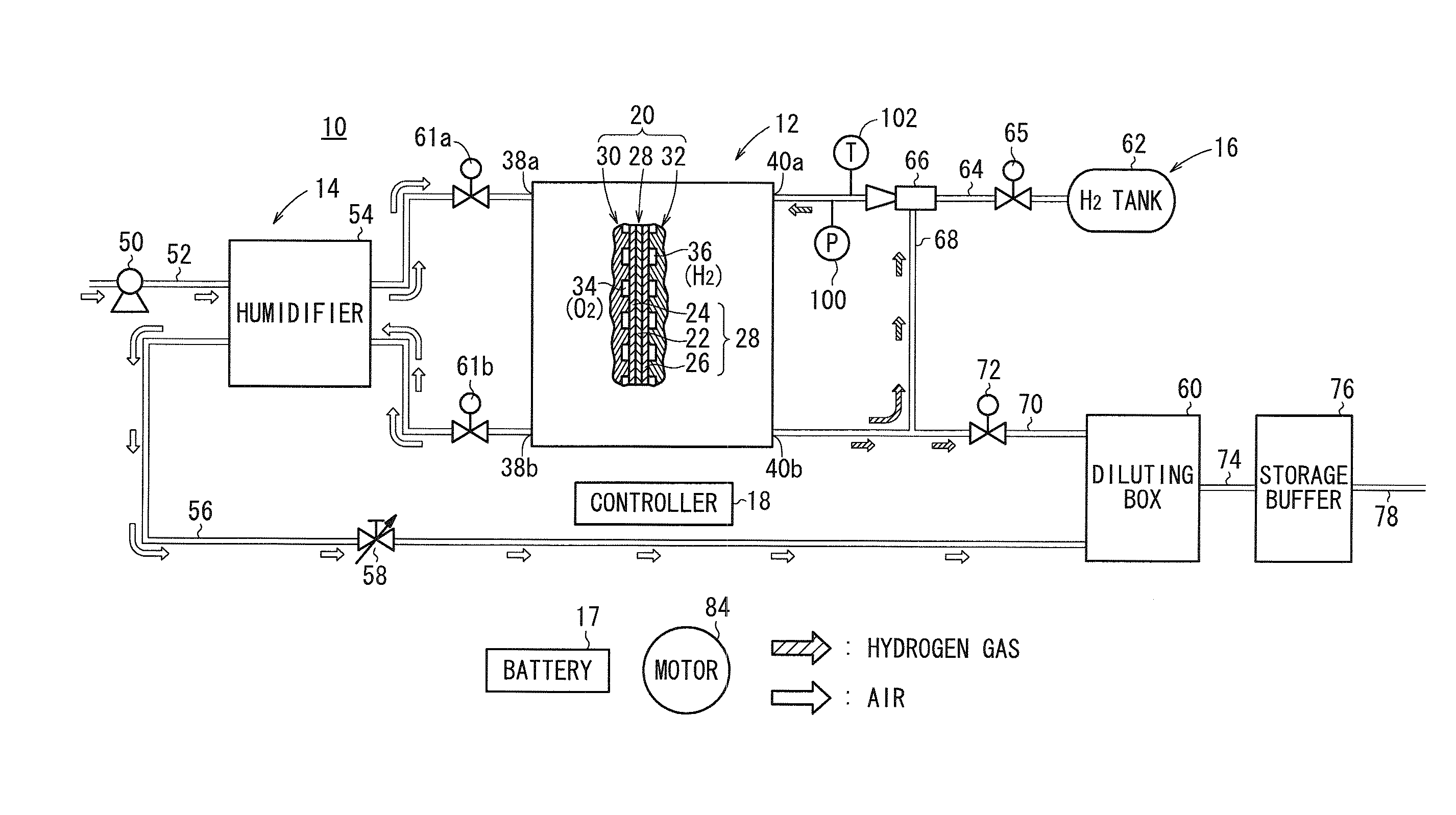
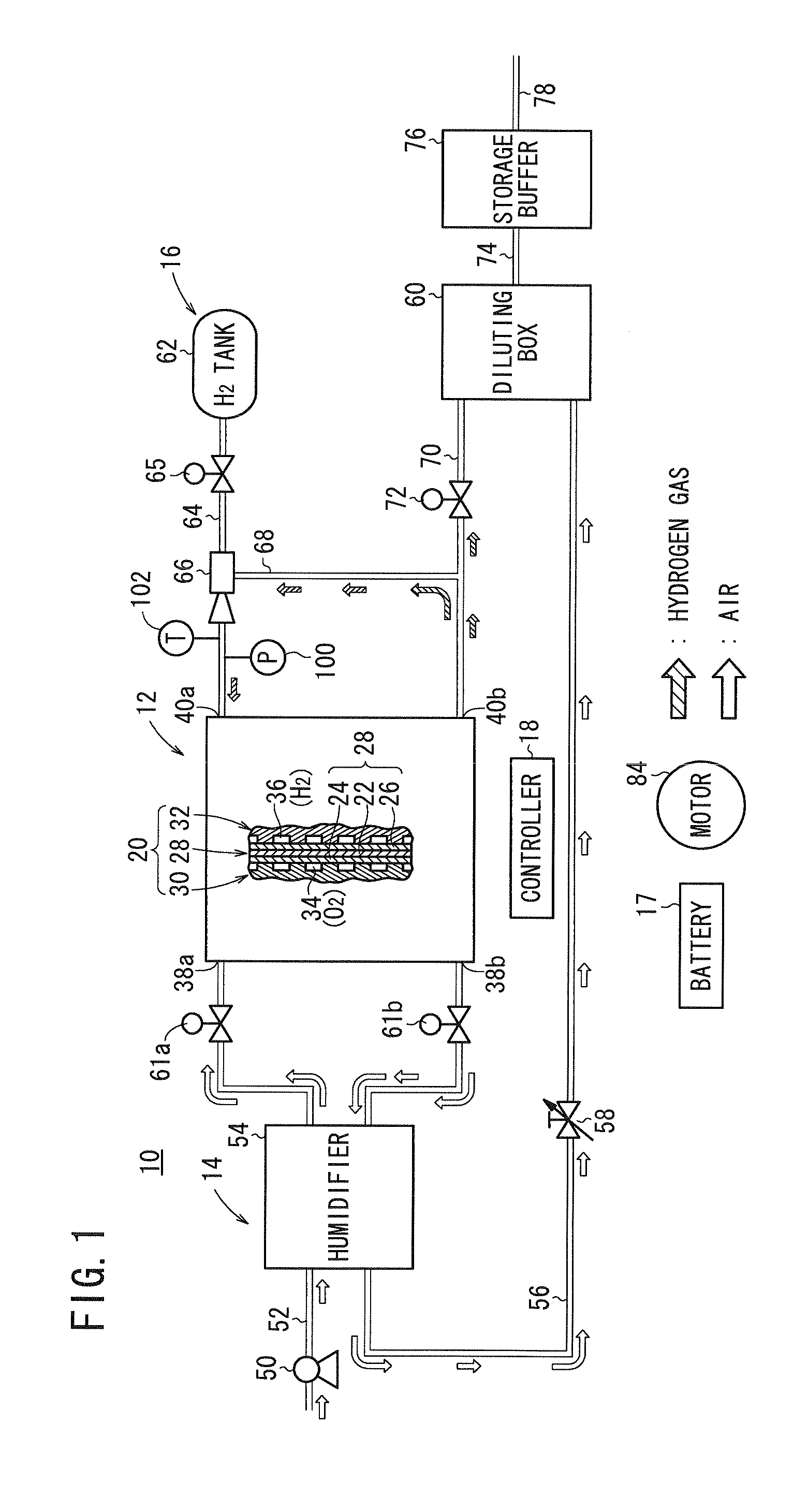
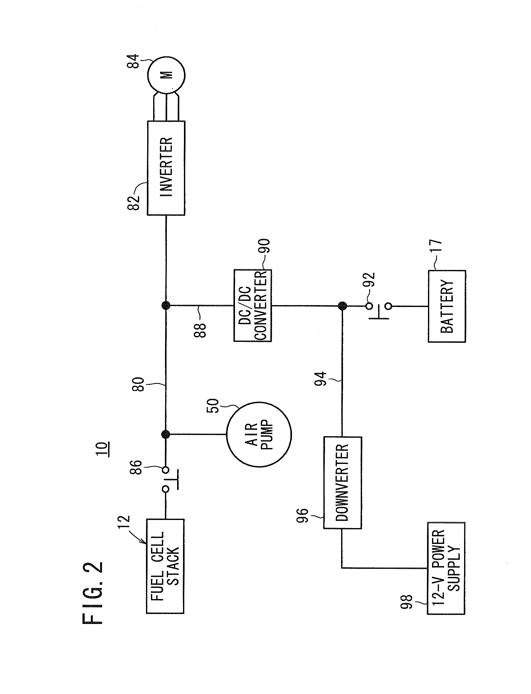
[0046]FIG. 1 schematically shows a fuel cell system 10 on which a method of shutting down a fuel cell system according to the present invention is carried out. As shown in FIG. 1, the fuel cell system 10 includes a fuel cell stack 12, an oxygen-containing gas supply device 14 for supplying an oxygen-containing gas to the fuel cell stack 12, a fuel gas supply device 16 for supplying a fuel gas to the fuel cell stack 12, a battery (electric storage device) 17 connectable to the fuel cell stack 12, and a controller 18 for controlling the fuel cell system 10 in its entirety. The fuel cell system 10 is mounted on a fuel cell vehicle such as a fuel cell automobile or the like. A battery 17 is capable of storing electricity for propelling the fuel cell vehicle under normal conditions. The battery 17 is capable of supplying a current of 20 A at a voltage of up to 500 V, which is higher in voltage power capacity than a 12-V power supply 98 (FIG. 2), to be described later.
[0047]The fuel cell ...
second embodiment
[0099]A method of shutting down the fuel cell system10 according to the present invention will be described below with reference to the timing chart shown in FIG. 11.
[0100]As described above, the fuel cell system 10, which is mounted on a fuel cell automobile (not shown), operates normally to propel the fuel cell automobile. When the ignition switch (not shown) of the fuel cell automobile is turned off, the method of shutting down the fuel cell system 10 is initiated.
[0101]First, the pressure at which hydrogen gas, i.e., a fuel gas, is supplied is preset in order to keep the fuel gas pressure in the fuel cell stack 12 at a preset pressure after a discharging process, to be described later, is carried out. More specifically, as shown in FIG. 12, a hydrogen gas volume region 110, which is filled with hydrogen gas and closed, includes the fuel gas flow field 36, the fuel gas inlet passage 40a, and the fuel gas outlet passage 40b in the fuel cell stack 12, a region of the hydrogen suppl...
third embodiment
[0118]FIG. 13 is a timing chart, which illustrates a method of shutting down a fuel cell system according to the present invention.
[0119]With the fuel cell system 10, the hydrogen pressure in the fuel cell stack 12 may drop before the discharging process commences, after the hydrogen pressure has risen to the desired anode pressure Pa (see the two-dot-and-dash-line curve in FIG. 13). This is because, for example, due to deterioration in performance of the fuel cells 20, hydrogen gas may pass from the fuel gas flow field 36 into the oxygen-containing gas flow field 34, thereby resulting in a reduction in hydrogen pressure. Accordingly, the hydrogen pressure may drop to or below the constant pressure Pb after completion of the discharging process.
[0120]On the other hand, due to a deterioration in performance of the fuel cells 20, the voltage (FC voltage) tends to be lowered (see the two-dot-and-dash-line curve in FIG. 13). During the discharging process, the FC voltage may even drop t...
PUM
 Abstract
Description
Claims
Application Information
 - Generate Ideas
- Intellectual Property
- Life Sciences
- Materials
- Tech Scout
- Unparalleled Data Quality
- Higher Quality Content
- 60% Fewer Hallucinations
Browse by: Latest US Patents, China's latest patents, Technical Efficacy Thesaurus, Application Domain, Technology Topic, Popular Technical Reports.
© 2025 PatSnap. All rights reserved.Legal|Privacy policy|Modern Slavery Act Transparency Statement|Sitemap|About US| Contact US: help@patsnap.com